Embedded Drivers & Real Time Operating Systems (Dr. Liu)
- LPC Lab Focuses [incomplete]
- GPIO
- Interrupts
- Lab Assignment: ADC + PWM
- Lab Assignment: Device Interfacing w/ SPI + Data Structures
- SPI
- Serial Peripheral Interface
- Pin Control and Pin Function Selection (LPC40xx)
- Structured Bit-fields Register Mapping
- SPI Lab
- UART
- I2C
- FreeRTOS
- Coding Standards
LPC Lab Focuses [incomplete]
Focus on optimal firmware in the following domains:
- Optimizing software for runtime
- Minimizing executable size
GPIO
Bit Manipulation
Bit-masking is a technique to selectively modify individual bits without affecting other bits.
Bit SET
To set a bit, we need to use the OR operator. This is just like an OR logical gate you should've learned in your Digital Design course.
// We want to set Bit #7 of a variable called: REG
REG = REG | 0x80;
// Let's set bit #31:
REG = REG | 0x80000000;
// Here is an easier way to write these:
// (1 << 31) means 1 gets shifted left 31 times to produce 0x80000000
REG = REG | (1 << 31);
// Simplify further:
REG |= (1 << 31);
// Set Bit #21 and Bit #23 at the same time
REG |= (1 << 21) | (1 << 23);Bit CLEAR
To set a bit to 0, in other words reset or clear a bit, the logic is similar, but instead of ORing a bit, we will an AND function to clear. Note: that ANDing something with 0 clears it and ANDing something with a 1 does not change it. The tilde (~) operator can help us invert the bits of a value in the following examples:
// Assume we want to reset Bit#7 of a register called: REG
REG = REG & 0x7F;
REG = REG & ~(0x80); // Same thing as above, but using ~ is easier
// Let's reset bit#31:
REG = REG & ~(0x80000000);
// Let's show you the easier way:
REG = REG & ~(1 << 31);
// Simplify further:
REG &= ~(1 << 31);
// Reset Bit#21 and Bit# 23:
REG &= ~( (1 << 21) | (1 << 23) );Bit TOGGLE
// Using XOR operator to toggle 5th bit
REG ^= (1 << 5);Bit CHECK
Suppose you want to check bit 7 of a register is set:
bool check_bit = REG & (1 << 7);
if(check_bit)
{
DoAThing();
}Now let's work through another example in which we want to wait until bit#9 is 0:
// One way:
while(REG & (1 << 9) != 0)
{
continue;
}
// Another way:
while(REG & (1 << 9))
{
continue;
}Multi-Bit Insertion
// Insert a set of continguous bits into a target value.
// Value within target is unknown. This is shown using X's
//
// target = 0xXXXX'XXXX
// ^
// /
// /
// value = 0xABCD --+
// position = 16
// width = 16
//
// return = 0xABCD'XXXX
// First you must clear the bits in that location
target &= ~(0xFFFF << 16);
// Now that there are only 0s from position 16 to 31, ew
// can OR those bits with our own set of 1s.
target |= (0xABCD << 16);Multi-Bit Extraction
/// Extract a set of contiguous bits from a target value.
///
/// target = 0x00FE'DCBA
/// ^
/// /
/// /
/// value = 4 -----------+
/// width = 8
///
/// return = 0xCB
// Shift target to the left by 4 to make the 0th bit the start of the bits you want to extract.
// Store the result in to a local variable
uint32_t result = target >> 4;
// Since we only want 8 bits from the result, we need to clear away the rest of the bits from
// the original target.
// AND the result with 0xFF, to clear everything except for the first 8 bits.
result = result & 0xFF;
LPC40xx Memory Map
What is a Memory Map
A memory map is a layout of how the memory maps to some set of information. With respect to embedded systems, the memory map we are concerned about maps out where the Flash (ROM), peripherals, interrupt vector table, SRAM, etc are located in address space.
Memory mapped IO
Memory mapped IO is a a means of mapping memory address space to devices external (IO) to the CPU, that is not memory.
For example (assuming a 32-bit system)
- Flash could be mapped to addresses 0x00000000 to 0x00100000 (1 Mbyte range)
- GPIO port could be located at address 0x1000000 (1 byte)
- Interrupt vector table could start from 0xFFFFFFFF and run backwards through the memory space
- SRAM gets the rest of the usable space (provided you have enough SRAM to fill that area)
It all depends on the CPU and the system designed around it.
Port Mapped IO
Port mapped IO uses additional signals from the CPU to qualify which signals are for memory and which are for IO. On Intel products, there is a (~M/IO) pin that is LOW when selecting MEMORY and HIGH when it is selecting IO.
The neat thing about using port mapped IO, is that you don't need to sacrifice memory space for IO, nor do you need to decode all 32-address lines. You can limit yourself to just using 8-bits of address space, which limits you to 256 device addresses, but that may be more than enough for your purposes.

Figure 2. Address Decoding with port map
(http://www.dgtal-sysworld.co.in/2012/04/memory-intercaing-to-8085.html)
LPC40xx memory map

Figure 3. LPC17xx Memory Map, which is nearly the same as the LPC40xx memory map
From this you can get an idea of which section of memory space is used for what. This can be found in the UM10562 LPC40xx user manual. If you take a closer look you will see that very little of the address space is actually taken up. With up to 4 billion+ address spaces (because 2^32 is a big number) to use you have a lot of free space to spread out your IO and peripherals.
Reducing the number of lines needed to decode IO
The LPC40xx chips, reduce bus line count, make all of the peripherals 32-bit aligned. Which means you must grab 4-bytes at a time. You cannot grab a single byte (8-bits) or a half-byte (16-bits) from memory. This eliminates the 2 least significant bits of address space.
Accessing IO using Memory Map in C
Please read the following code snippet. This is runnable on your system now. Just copy and paste it into your main.cpp file.
//The goal of this software is to set the GPIO pin P1.0 to
// low then high after some time. Pin P1.0 is connected to an LED.
// The address to set the direction for GPIOs in port 1 is below:
//
// FIO1DIR = 0x2009C020
//
// The address to set the output value of a pin in port 1 is below:
//
// FIO1PIN = 0x2009C034
#include <cstdint>
volatile uint32_t * const FIO1DIR = (uint32_t *)(0x2009C020);
volatile uint32_t * const FIO1PIN = (uint32_t *)(0x2009C034);
int main(void)
{
// Set 0th bit, setting Pin 0.0 to an output pin
*FIO1DIR |= (1 << 0);
// Set 0th bit, setting Pin 0.0 to high
*FIO1PIN &= ~(1 << 0);
// Loop for a while (volatile is needed, otherwise this will not loop for very long!)
for(volatile uint32_t i = 0; i < 1000000; i++);
// Clear 0th bit, setting Pin 0.0 to low
*FIO1PIN |= (1 << 0);
return 0;
}volatile keyword tells the compiler not to optimize this variable out, even if it seems useless
const keyword tells the compiler that this variable cannot be modified
Notice "const" placement and how it is placed after the uint32_t *. This is because we want to make sure the pointer address never changes and remains constant, but the value that it references should be modifiable.
Using the LPC40xx.h
The above is nice and it works, but its a lot of work. You have to go back to the user manual to see which addresses are for what register. There must be some better way!!
Take a look at the LPC40xx.h file, which It is located in the SJSU-Dev/firmware/library/L0_LowLevel/LPC40xx.h. Here you will find definitions for each peripheral memory address in the system.
Lets say you wanted to port the above code to something a bit more structured:
- Open up "LPC40xx.h"
- Search for "GPIO"
- You will find a struct with the name LPC_GPIO_TypeDef.
- Now search for "LPC_GPIO_TypeDef" with a #define in the same line.
- You will see that LPC_GPIO_TypeDef is a pointer of these structs
#define LPC_GPIO0 ((LPC_GPIO_TypeDef *) LPC_GPIO0_BASE )#define LPC_GPIO1 ((LPC_GPIO_TypeDef *) LPC_GPIO1_BASE )#define LPC_GPIO2 ((LPC_GPIO_TypeDef *) LPC_GPIO2_BASE )#define LPC_GPIO3 ((LPC_GPIO_TypeDef *) LPC_GPIO3_BASE )#define LPC_GPIO4 ((LPC_GPIO_TypeDef *) LPC_GPIO4_BASE )
- We want to use LPC_GPIO1 since that corrisponds to GPIO port 1.
- If you inspect LPC_GPIO_TypeDef, you can see the members that represent register FIODIR and FIOPIN
- You can now access FIODIR and FIOPIN in the following way:
#include "LPC40xx.h"
int main(void)
{
// Set direction of P0.0 to 1, which means OUTPUT
LPC_GPIO1->FIODIR |= (1 << 0);
// Set 0th bit, setting Pin 0.0 to high
LPC_GPIO1->FIOPIN &= ~(1 << 0);
for(volatile uint32_t i = 0; i < 1000000; i++);
// Clear 0th bit, setting Pin 0.0 to low
LPC_GPIO1->FIOPIN |= (1 << 0);
return 0;
}At first this may get tedious, but once you get more experience, you won't open the LPC40xx.h file very often. This is the preferred way to access registers in this course.
On occasions, the names of registers in the user manual are not exactly the same in this file.
General Purpose Input Output
Objective
To be able to General Purpose Input Output (GPIO), to generate digital output signals and to read input signals. Digital outputs can be used as control signals to other hardware, to transmit information, to signal another computer/controller, to activate a switch or, with sufficient current, to turn on or off LEDs or to make a buzzer sound.
Below will be a discussion on using GPIO to drive an LED.
Although the interface may seem simple, you do need to consider hardware design and know some of the fundamental of electricity. There are a couple of goals for us:
- No hardware damage if faulty firmware is written.
- Circuit should prevent excess amount of current to avoid processor damage.
Required Background
You should know the following:
- bit-masking in C
- wire-wrapping or use of a breadboard
- Fundamentals of electricity such as Ohm's law (V = IR) and how diodes work.
GPIO

Figure 1. Internal Design of a GPIO
GPIO stands for "General Purpose Input Output". Each pin can at least be used as an output or input. In an output configuration, the pin voltage is either 0v or 3.3v. In input mode, we can read whether the voltage is 0v or 3.3v.
You can locate a GPIO that you wish to use for a switch or an LED by first starting with the schematic of the board. The schematic will show which pins are "available" because some of the microcontroller pins may be used internally by your development board. After you locate a free pin, such as P2.0, then you can look-up the microcontroller user manual to locate the memory that you can manipulate.
Hardware Registers Coding
The hardware registers map to physical pins. If we want to attach our switch and the LED to our microcontroller's PORT0, then here are the relevant registers and their functionality :
| LPC17xx Port0 Registers | |
| LPC_GPIO0->FIODIR | Direction of the port pins, 1 = output |
| LPC_GPIO0->FIOPIN |
Read: Sensed inputs of the port pins, 1 = HIGH Write: Control voltage level of the pin, 1 = 3.3v |
| LPC_GPIO0->FIOSET | Write only: Any bits written 1 are OR'd with FIOPIN |
| LPC_GPIO0->FIOCLR | Write only: Any bits written 1 are AND'd with FIOPIN |
Switch
We will interface our switch to PORT0.2, or port zero's 3rd pin (counting from 0).
Note that the "inline" resistor is used such that if your GPIO is mis-configured as an OUTPUT pin, hardware damage will not occur from badly written software.

// Set the direction of P0.2 to input
LPC_GPIO0->FIODIR &= ~(1 << 2);
// Now, simply read the 32-bit FIOPIN registers, which corresponds to
// 32 physical pins of PORT 0.
// Use AND logic to test if JUST the pin number 2 of port zero is set.
if (LPC_GPIO0->FIOPIN & (1 << 2))
{
// Switch is logical HIGH
}
else
{
// Switch is logical LOW
}LED
We will interface our LED to PORT0.3, or port zero's 4th pin (counting from 0).
Given below are two configurations of an LED. Usually, the "sink" current is higher than "source", hence the active-low configuration is used more often.
|
Figure 3. Active High LED circuit schematic |
Figure 4. Active low LED circuit schematic |


// Make direction of PORT0.3 as OUTPUT
LPC_GPIO0->FIODIR |= (1 << 3);
// Setting bit 3 to 1 of IOPIN will turn ON LED
// and resetting to 0 will turn OFF LED.
LPC_GPIO0->FIOPIN |= (1 << 3);
// An alternative way, is to use the FIOSET and FIOCLR registers (no OR logic needed)
LPC_GPIO0->FIOSET = (1 << 3);
// Likewise, reset to 0
LPC_GPIO0->FIOCLR = (1 << 3);GPIO Lab Assignment
Objective
Gain experience doing the following:
- Manipulating a registers in order to access and control physical pins
- Use implemented driver to sense input signals and control LEDs.
Assignment
Test your knowledge by doing the following:
Part 0. Basic GPIO Driver to blink an onboard LED
int main()
{
// 1) Find and choose an onboard LED to manipluate.
// 2) Use the schematic to figure out which pin it is connected to
// 3) Use FIODIR to set that pin as an output
while (true)
{
// 4) use FIOCLR to set the pin LOW, turning ON the LED
LOG_INFO("Turning LED ON!");
Delay(500); // Delay in milliseconds
// 5) use FIOSET to set the pin HIGH, turning OFF the LED
LOG_INFO("Turning LED OFF!");
Delay(500);
}
return 0;
}Part 1. Implement the LabGPIO Driver
Using the following class template
- Implement ALL class methods.
- All methods must function work as expected of their method name.
- Must be able to handle pins in port 0, 1, and 2.
#pragma once
#include <cstdint>
class LabGPIO
{
public:
enum class Direction : uint8_t
{
kInput = 0,
kOutput = 1
};
enum class State : uint8_t
{
kLow = 0,
kHigh = 1
};
/// You should not modify any hardware registers at this point
/// You should store the port and pin using the constructor.
///
/// @param port - port number between 0 and 5
/// @param pin - pin number between 0 and 32
constexpr LabGPIO(uint8_t port, uint8_t pin);
/// Sets this GPIO as an input
void SetAsInput();
/// Sets this GPIO as an output
void SetAsOutput();
/// Sets this GPIO as an input
/// @param output - true => output, false => set pin to input
void SetDirection(Direction direction);
/// Set voltage of pin to HIGH
void SetHigh();
/// Set voltage of pin to LOW
void SetLow();
/// Set pin state to high or low depending on the input state parameter.
/// Has no effect if the pin is set as "input".
///
/// @param state - State::kHigh => set pin high, State::kLow => set pin low
void set(State state);
/// Should return the state of the pin (input or output, doesn't matter)
///
/// @return level of pin high => true, low => false
State Read();
/// Should return the state of the pin (input or output, doesn't matter)
///
/// @return level of pin high => true, low => false
bool ReadBool();
private:
/// port, pin and any other variables should be placed here.
/// NOTE: Pin state should NEVER be cached! Always check the hardware
/// registers for the actual value of the pin.
};
Part 2. Use Driver for an application
The application is to use all 4 internal buttons to control the on board LEDs above them.
int main(void)
{
LabGpio button0(?, ?);
LabGpio led0(?, ?);
// Initialize button and led here
while(true)
{
// Logic to read if button has been RELEASED and if so, TOGGLE LED state;
}
return 0;
}Requirements:
You MUST NOT use any pre-existing library such as a GPIO class for this assignment.
You MAY USE LPC40xx.h as it is not a library but a list of registers mapped to the appropriate locations.
The code must read from the internal button. If a button is RELEASED, toggle the state of the LED.
Upload only relevant source files into canvas. A good example is: main.cpp, LabGPIO.hpp, LabGPIO.cpp. See Canvas for rubric and grade breakdown.
Extra Credit
Add a flashy easter egg feature to your assignment, with your new found LED and switch powers! The extra credit is subject to the instructor's, ISA's and TA's discretion about what is worth the extra credit.
Consider using additional switches and/or LEDs.
Interrupts
C++ Keywords
Sections of a binary
.text
Assembly instructions are placed within this section. When loaded onto a board, this will section will be placed into the flash memory (ROM) of the board. The binary file (.bin) that you load onto you board includes all of this information in it. The more code you write, the bigger the binary size gets.
.data
All global initialized variables are placed in this section. When the binary is created, in order to know what those global variables were at compile time, they are put into the binary which takes space on the ROM. At runtime, when the embedded system turns on, it moves the .data contents from the ROM to RAM so it can be used and modified by the application.
.bss
Section contains information about all uninitialized global variables. This will take up a small section in ROM, in that it only includes the start position in RAM and its length. The embedded platform will write zeros to to the start of that RAM location, extending its whole length. The .bss section must be cleared before using any newlib (stdclib and stdc++lib) libraries:
Reference: https://www.embecosm.com/appnotes/ean9/ean9-howto-newlib-1.0.html#id2717944
Const
Out of all of the discussed keywords, const is probably the most commonly known keyword because of its simplicity as well as its ubiquity across many languages. But does it REALLY mean for a variable, class, or structure to be const?
Resource: https://en.cppreference.com/w/cpp/language/cv
As a Global Variable on an Embedded Platform
Take the following code:
const uint32_t kConstantVariable = 5;
int main(void)
{
// ...
return 0;
}What effect does the const in front of the variable type change the variable?
- Does not allow the variable to be modified. Will throw a compiler error.
- Will be place the variable in ROM (or .text section).
- Removing the const will place
As a Local Variable on an Embedded Platform
- Compiler will not allow modification of the variable.
- Will be placed in the STACK as per a typical function call.
Cheating the system
const uint32_t kConstVariable = 5;
void AttemptToModifyConst()
{
uint32_t * const_pointer = const_cast<uint32_t*>(&kConstVariable);
*const_pointer = 10; // Should cause system fault. Do not try this.
const uint32_t kLocalConstVariable = 15;
uint32_t * local_const_pointer = const_cast<uint32_t*>(&kLocalConstVariable);
*local_const_pointer = 10; // Should NOT cause system fault, but defeats the purpose of using const in the first place.
}If you cast away the const of a variable, you can attempt to change it. If the variable is global and placed in ROM, this will attempt a write access to the ROM which will cause a system fault. Doing so to local variables, which exists on the STACK which is within ram does not cause any faults, because the memory was always mutable. In the case of local variables, const is a means to keep you from compiling code that changes a constant.
Benefits of using Const in Embedded
If you evaluate many MCUs, you will see that most of them have a decent amount of flash but small amounts of RAM. If you have information that does not need to be modified at run time, you can shift the information into the ROM by placing it in global space (or make it static, see static section). This is why you should make you character strings, lookup tables, bitmaps and anything else const.
// Examples of good use cases for
const char kIpAddress = "192.168.1.5";
const char kUrl = "http://example.com/index.html";
const uint32_t kBitMasks[] = { 0xF0F0F0F, 0x55555555, 0xAAAAAAAA };
const uint8_t kMaximumRetries = 10;Volatile
Every access to volatile variable will be treated as a visible side-effect. This means that:
- The compiler CANNOT do optimizations such as out-of-order instruction reordering, link time garbage collection of the object or as-if transformations.
- Access to object WILL bypass CPU cache and generate a bus cycle.
volatile uint32_t * pin_address = &LPC_GPIO0->PIN;
// Pin address will be loaded from the system bus and written back to the system bus.
// No caching will take place.
*pin_address |= (1 << 5);Benefits of using Volatile in Embedded
- Required in order to insure that access of registers is not optimized out.
- Prevents the register information from being access through the cache. To change a register, you need to write to it, but if you make the changes to cache memory, the actual hardware isn't read or written to.
Inline
Many people make the mistake in C++ in thinking that the inline keyword means that the contents of a function call will be inlined at the call site. This is not correct. In order to make this happen you must use the always_inline compiler attribute.
How define a function that will be inlined at its call site
// Modern C++17 and above attribute
[[gnu::always_inline]]
void CallsiteInlinedFunction(int a, int b)
{
return a + b;
}
// Older version of GCC will require this
// Must seperate the attributes from the declaration
__attribute__((always_inline))
void CallsiteInlinedFunctionOld(int a, int b);
void CallsiteInlinedFunctionOld(int a, int b)
{
return a + b;
}Inline functions and variables within header files
Inline functions and variables can be defined within a header file without the need to define them in a .cpp file. The will keep linker errors from appearing
TODO: Add more detail as the above lacks it.
For member variables in class/structs
Static variables can be defined within a class if their declaration is preceded by the inline keyword.
Static
The static keyword has a load of different meanings depending on where it is used.
Static global variable or function
// Objects below are not visible outside of the .cpp file.
// Techincally works in .h/.hpp files but it defeats the purpose of putting it in there.
static uint8_t kHiddenBuffer[256];
static void FunctionPrivateToThisFile()
{
// ...
}Stay away from using static this way in C++. If you would like to make a variable, object, type, etc private to a file you can use an anonymous namespace.
namespace
{
// Objects below are not visible outside of the .cpp file.
// Techincally works in .h/.hpp files but it defeats the purpose of putting it in there.
uint8_t kHiddenBuffer[256];
void FunctionPrivateToThisFile()
{
// ...
}
} // namespaceStatic local function/method variable
Static variables within a function are actually apart of the .data section and not the stack. The also retain values across calls. This variable can be considered the state of the function.
uint32_t FunctionWithInternalStateVariable()
{
static uint32_t call_count = 0;
return ++call_count;
}Static class/struct member variable
class ClassWithStaticVariable
{
public:
ClassWithStaticVariable()
{
// NOTE: that this is NOT thread safe!
id = next_id++;
}
// ...
private:
// This variable is common and accessable by all objects of this class
// So if one class alters it, each class will see that change.
inline static uint32_t next_id = 0;
uint32_t id;
};
Enum Class
You may be familiar with enumerations in C and C++. What enumeration class does is make enumerations strong types.
// A clever way to force the user to your enumeration
// vs them potentially putting in an invalid value.
enum class TransferSpeed : uint32_t
{
kHigh = 0b011,
kFast = 0b010,
kLow = 0b001,
kDisabled = 0b111,
};
void SetTransferSpeed(TransferSpeed speed)
{
// Because speed is not a integer type, you need to cast it into that type.
*transfer_speed_register = static_cast<uint32_t>(speed);
}
// Usage ...
SetTransferSpeed(TransferSpeed::kHigh); // OK
SetTransferSpeed(TransferSpeed::kFast); // OK
SetTransferSpeed(0b00); // Compiler Error!
Constexpr
Variables and function declared with the constexpr keyword exist only at compile time.
// Should return a mask like so:
// AlternatingPatternMask(1) => 0b...0101'0101'0101'0101
// AlternatingPatternMask(2) => 0b...1011'0110'1101'1011
// AlternatingPatternMask(3) => 0b...0111'0111'0111'0111
// etc ...
constexpr uint32_t AlternatingPatternMask(uint8_t number_of_ones_in_sequence)
{
uint32_t result = 0;
for (int i = 0; i < sizeof(uint16_t)*8; i++)
{
uint32_t set_this_bit = ((i % number_of_ones_in_sequence) == 0) ? 0 : 1;
result |= set_this_bit << i;
}
return result;
}
// ...
// This value of this global variable is figured out at compile
// time and not at runtime.
// NOTE: this depends on the situation in which it is used.
uint32_t three_ones_in_sequence_mask = AlternatingPatternMask(3);Using
TODO: Fill this out later
Lookup Tables
Objective
To discuss lookup tables and how to use them to sacrifice storage space to increase computation time.
What Are Lookup Tables
Lookup tables are static arrays that sacrifices memory storage in place of a simple array index lookup of precalculated values. In some examples, a lookup table is not meant to speed a process, but simply an elegant solution to a problem.
Lets look at some examples to see why these are useful.
Why Use Lookup Tables
Simple Example: Convert Potentiometer Voltage to Angle
Lets make some assumptions about the system first:
- Using an 8-bit ADC
- Potentiometer is linear
- Potentiometer sweep angle is 180 degrees
- Potentiometer all the way left is 0 deg and 0V
- Potentiometer all the way right (180 deg) is ADC Reference Voltage
- Using a processor that does NOT have a FPU (Floating Point arithmetic Unit) like the Arm Cortex M3 we use in the LPC1756.
double potADCToDegrees(uint8_t adc)
{
return ((double)(adc))*(270/256);
}Code Block 1. Without Lookup
const double potentiometer_angles[256] =
{
// [ADC] = Angle
[0] = 0.0,
[1] = 1.0546875,
[2] = 2.109375,
[3] = 3.1640625,
[4] = 4.21875,
[5] = 5.2734375,
[6] = 6.328125,
[7] = 7.3828125,
[8] = 8.4375,
[9] = 9.4921875,
[10] = 10.546875,
[11] = 11.6015625,
[12] = 12.65625,
[13] = 13.7109375,
[14] = 14.765625,
[15] = 15.8203125,
[16] = 16.875,
[17] = 17.9296875,
[18] = 18.984375,
[19] = 20.0390625,
[20] = 21.09375,
[21] = 22.1484375,
[22] = 23.203125,
[23] = 24.2578125,
[24] = 25.3125,
[25] = 26.3671875,
[26] = 27.421875,
[27] = 28.4765625,
[28] = 29.53125,
[29] = 30.5859375,
[30] = 31.640625,
[31] = 32.6953125,
[32] = 33.75,
[33] = 34.8046875,
[34] = 35.859375,
[35] = 36.9140625,
[36] = 37.96875,
[37] = 39.0234375,
[38] = 40.078125,
[39] = 41.1328125,
[40] = 42.1875,
[41] = 43.2421875,
[42] = 44.296875,
[43] = 45.3515625,
[44] = 46.40625,
[45] = 47.4609375,
[46] = 48.515625,
[47] = 49.5703125,
[48] = 50.625,
[49] = 51.6796875,
[50] = 52.734375,
[51] = 53.7890625,
[52] = 54.84375,
[53] = 55.8984375,
[54] = 56.953125,
[55] = 58.0078125,
[56] = 59.0625,
[57] = 60.1171875,
[58] = 61.171875,
[59] = 62.2265625,
[60] = 63.28125,
[61] = 64.3359375,
[62] = 65.390625,
[63] = 66.4453125,
[64] = 67.5,
[65] = 68.5546875,
[66] = 69.609375,
[67] = 70.6640625,
[68] = 71.71875,
[69] = 72.7734375,
[70] = 73.828125,
[71] = 74.8828125,
[72] = 75.9375,
[73] = 76.9921875,
[74] = 78.046875,
[75] = 79.1015625,
[76] = 80.15625,
[77] = 81.2109375,
[78] = 82.265625,
[79] = 83.3203125,
[80] = 84.375,
[81] = 85.4296875,
[82] = 86.484375,
[83] = 87.5390625,
[84] = 88.59375,
[85] = 89.6484375,
[86] = 90.703125,
[87] = 91.7578125,
[88] = 92.8125,
[89] = 93.8671875,
[90] = 94.921875,
[91] = 95.9765625,
[92] = 97.03125,
[93] = 98.0859375,
[94] = 99.140625,
[95] = 100.1953125,
[96] = 101.25,
[97] = 102.3046875,
[98] = 103.359375,
[99] = 104.4140625,
[100] = 105.46875,
[101] = 106.5234375,
[102] = 107.578125,
[103] = 108.6328125,
[104] = 109.6875,
[105] = 110.7421875,
[106] = 111.796875,
[107] = 112.8515625,
[108] = 113.90625,
[109] = 114.9609375,
[110] = 116.015625,
[111] = 117.0703125,
[112] = 118.125,
[113] = 119.1796875,
[114] = 120.234375,
[115] = 121.2890625,
[116] = 122.34375,
[117] = 123.3984375,
[118] = 124.453125,
[119] = 125.5078125,
[120] = 126.5625,
[121] = 127.6171875,
[122] = 128.671875,
[123] = 129.7265625,
[124] = 130.78125,
[125] = 131.8359375,
[126] = 132.890625,
[127] = 133.9453125,
[128] = 135,
[129] = 136.0546875,
[130] = 137.109375,
[131] = 138.1640625,
[132] = 139.21875,
[133] = 140.2734375,
[134] = 141.328125,
[135] = 142.3828125,
[136] = 143.4375,
[137] = 144.4921875,
[138] = 145.546875,
[139] = 146.6015625,
[140] = 147.65625,
[141] = 148.7109375,
[142] = 149.765625,
[143] = 150.8203125,
[144] = 151.875,
[145] = 152.9296875,
[146] = 153.984375,
[147] = 155.0390625,
[148] = 156.09375,
[149] = 157.1484375,
[150] = 158.203125,
[151] = 159.2578125,
[152] = 160.3125,
[153] = 161.3671875,
[154] = 162.421875,
[155] = 163.4765625,
[156] = 164.53125,
[157] = 165.5859375,
[158] = 166.640625,
[159] = 167.6953125,
[160] = 168.75,
[161] = 169.8046875,
[162] = 170.859375,
[163] = 171.9140625,
[164] = 172.96875,
[165] = 174.0234375,
[166] = 175.078125,
[167] = 176.1328125,
[168] = 177.1875,
[169] = 178.2421875,
[170] = 179.296875,
[171] = 180.3515625,
[172] = 181.40625,
[173] = 182.4609375,
[174] = 183.515625,
[175] = 184.5703125,
[176] = 185.625,
[177] = 186.6796875,
[178] = 187.734375,
[179] = 188.7890625,
[180] = 189.84375,
[181] = 190.8984375,
[182] = 191.953125,
[183] = 193.0078125,
[184] = 194.0625,
[185] = 195.1171875,
[186] = 196.171875,
[187] = 197.2265625,
[188] = 198.28125,
[189] = 199.3359375,
[190] = 200.390625,
[191] = 201.4453125,
[192] = 202.5,
[193] = 203.5546875,
[194] = 204.609375,
[195] = 205.6640625,
[196] = 206.71875,
[197] = 207.7734375,
[198] = 208.828125,
[199] = 209.8828125,
[200] = 210.9375,
[201] = 211.9921875,
[202] = 213.046875,
[203] = 214.1015625,
[204] = 215.15625,
[205] = 216.2109375,
[206] = 217.265625,
[207] = 218.3203125,
[208] = 219.375,
[209] = 220.4296875,
[210] = 221.484375,
[211] = 222.5390625,
[212] = 223.59375,
[213] = 224.6484375,
[214] = 225.703125,
[215] = 226.7578125,
[216] = 227.8125,
[217] = 228.8671875,
[218] = 229.921875,
[219] = 230.9765625,
[220] = 232.03125,
[221] = 233.0859375,
[222] = 234.140625,
[223] = 235.1953125,
[224] = 236.25,
[225] = 237.3046875,
[226] = 238.359375,
[227] = 239.4140625,
[228] = 240.46875,
[229] = 241.5234375,
[230] = 242.578125,
[231] = 243.6328125,
[232] = 244.6875,
[233] = 245.7421875,
[234] = 246.796875,
[235] = 247.8515625,
[236] = 248.90625,
[237] = 249.9609375,
[238] = 251.015625,
[239] = 252.0703125,
[240] = 253.125,
[241] = 254.1796875,
[242] = 255.234375,
[243] = 256.2890625,
[244] = 257.34375,
[245] = 258.3984375,
[246] = 259.453125,
[247] = 260.5078125,
[248] = 261.5625,
[249] = 262.6171875,
[250] = 263.671875,
[251] = 264.7265625,
[252] = 265.78125,
[253] = 266.8359375,
[254] = 267.890625,
[255] = 270
};
inline double potADCToDegrees(uint8_t adc)
{
return potentiometer_angles[adc];
}Code Block 2. With Lookup
With the two examples, it may seem trivial since the WITHOUT case is only "really" doing one calculation, mulitplying the uint8_t with (270/256) since the compiler will most likely optimize this value to its result. But if you take a look at the assembly, the results may shock you.
Look up Table Disassembly
00016e08 <main>:
main():
/var/www/html/SJSU-Dev/firmware/Experiements/L5_Application/main.cpp:322
[254] = 268.9411765,
[255] = 270
};
int main(void)
{
16e08: b082 sub sp, #8
/var/www/html/SJSU-Dev/firmware/Experiements/L5_Application/main.cpp:323
volatile double a = potentiometer_angles[15];
16e0a: a303 add r3, pc, #12 ; (adr r3, 16e18 <main+0x10>)
16e0c: e9d3 2300 ldrd r2, r3, [r3]
16e10: e9cd 2300 strd r2, r3, [sp]
16e14: e7fe b.n 16e14 <main+0xc>
16e16: bf00 nop
16e18: c3b9a8ae .word 0xc3b9a8ae
16e1c: 402fc3c3 .word 0x402fc3c3Code Block 3. Dissassembly of Look up Table
Looks about right. You can see at 16e0a the software is retrieving data from the lookup table, and then it is loading it into the double which is on the stack.
Double Floating Point Disassembly
00017c64 <__adddf3>:
__aeabi_dadd():
17c64: b530 push {r4, r5, lr}
17c66: ea4f 0441 mov.w r4, r1, lsl #1
17c6a: ea4f 0543 mov.w r5, r3, lsl #1
17c6e: ea94 0f05 teq r4, r5
17c72: bf08 it eq
17c74: ea90 0f02 teqeq r0, r2
17c78: bf1f itttt ne
17c7a: ea54 0c00 orrsne.w ip, r4, r0
17c7e: ea55 0c02 orrsne.w ip, r5, r2
17c82: ea7f 5c64 mvnsne.w ip, r4, asr #21
17c86: ea7f 5c65 mvnsne.w ip, r5, asr #21
17c8a: f000 80e2 beq.w 17e52 <__adddf3+0x1ee>
17c8e: ea4f 5454 mov.w r4, r4, lsr #21
17c92: ebd4 5555 rsbs r5, r4, r5, lsr #21
17c96: bfb8 it lt
17c98: 426d neglt r5, r5
17c9a: dd0c ble.n 17cb6 <__adddf3+0x52>
17c9c: 442c add r4, r5
17c9e: ea80 0202 eor.w r2, r0, r2
17ca2: ea81 0303 eor.w r3, r1, r3
17ca6: ea82 0000 eor.w r0, r2, r0
17caa: ea83 0101 eor.w r1, r3, r1
17cae: ea80 0202 eor.w r2, r0, r2
17cb2: ea81 0303 eor.w r3, r1, r3
17cb6: 2d36 cmp r5, #54 ; 0x36
17cb8: bf88 it hi
17cba: bd30 pophi {r4, r5, pc}
17cbc: f011 4f00 tst.w r1, #2147483648 ; 0x80000000
17cc0: ea4f 3101 mov.w r1, r1, lsl #12
17cc4: f44f 1c80 mov.w ip, #1048576 ; 0x100000
17cc8: ea4c 3111 orr.w r1, ip, r1, lsr #12
17ccc: d002 beq.n 17cd4 <__adddf3+0x70>
17cce: 4240 negs r0, r0
17cd0: eb61 0141 sbc.w r1, r1, r1, lsl #1
17cd4: f013 4f00 tst.w r3, #2147483648 ; 0x80000000
17cd8: ea4f 3303 mov.w r3, r3, lsl #12
17cdc: ea4c 3313 orr.w r3, ip, r3, lsr #12
17ce0: d002 beq.n 17ce8 <__adddf3+0x84>
17ce2: 4252 negs r2, r2
17ce4: eb63 0343 sbc.w r3, r3, r3, lsl #1
17ce8: ea94 0f05 teq r4, r5
17cec: f000 80a7 beq.w 17e3e <__adddf3+0x1da>
17cf0: f1a4 0401 sub.w r4, r4, #1
17cf4: f1d5 0e20 rsbs lr, r5, #32
17cf8: db0d blt.n 17d16 <__adddf3+0xb2>
17cfa: fa02 fc0e lsl.w ip, r2, lr
17cfe: fa22 f205 lsr.w r2, r2, r5
17d02: 1880 adds r0, r0, r2
17d04: f141 0100 adc.w r1, r1, #0
17d08: fa03 f20e lsl.w r2, r3, lr
17d0c: 1880 adds r0, r0, r2
17d0e: fa43 f305 asr.w r3, r3, r5
17d12: 4159 adcs r1, r3
17d14: e00e b.n 17d34 <__adddf3+0xd0>
17d16: f1a5 0520 sub.w r5, r5, #32
17d1a: f10e 0e20 add.w lr, lr, #32
17d1e: 2a01 cmp r2, #1
17d20: fa03 fc0e lsl.w ip, r3, lr
17d24: bf28 it cs
17d26: f04c 0c02 orrcs.w ip, ip, #2
17d2a: fa43 f305 asr.w r3, r3, r5
17d2e: 18c0 adds r0, r0, r3
17d30: eb51 71e3 adcs.w r1, r1, r3, asr #31
17d34: f001 4500 and.w r5, r1, #2147483648 ; 0x80000000
17d38: d507 bpl.n 17d4a <__adddf3+0xe6>
17d3a: f04f 0e00 mov.w lr, #0
17d3e: f1dc 0c00 rsbs ip, ip, #0
17d42: eb7e 0000 sbcs.w r0, lr, r0
17d46: eb6e 0101 sbc.w r1, lr, r1
17d4a: f5b1 1f80 cmp.w r1, #1048576 ; 0x100000
17d4e: d31b bcc.n 17d88 <__adddf3+0x124>
17d50: f5b1 1f00 cmp.w r1, #2097152 ; 0x200000
17d54: d30c bcc.n 17d70 <__adddf3+0x10c>
17d56: 0849 lsrs r1, r1, #1
17d58: ea5f 0030 movs.w r0, r0, rrx
17d5c: ea4f 0c3c mov.w ip, ip, rrx
17d60: f104 0401 add.w r4, r4, #1
17d64: ea4f 5244 mov.w r2, r4, lsl #21
17d68: f512 0f80 cmn.w r2, #4194304 ; 0x400000
17d6c: f080 809a bcs.w 17ea4 <__adddf3+0x240>
17d70: f1bc 4f00 cmp.w ip, #2147483648 ; 0x80000000
17d74: bf08 it eq
17d76: ea5f 0c50 movseq.w ip, r0, lsr #1
17d7a: f150 0000 adcs.w r0, r0, #0
17d7e: eb41 5104 adc.w r1, r1, r4, lsl #20
17d82: ea41 0105 orr.w r1, r1, r5
17d86: bd30 pop {r4, r5, pc}
17d88: ea5f 0c4c movs.w ip, ip, lsl #1
17d8c: 4140 adcs r0, r0
17d8e: eb41 0101 adc.w r1, r1, r1
17d92: f411 1f80 tst.w r1, #1048576 ; 0x100000
17d96: f1a4 0401 sub.w r4, r4, #1
17d9a: d1e9 bne.n 17d70 <__adddf3+0x10c>
17d9c: f091 0f00 teq r1, #0
17da0: bf04 itt eq
17da2: 4601 moveq r1, r0
17da4: 2000 moveq r0, #0
17da6: fab1 f381 clz r3, r1
17daa: bf08 it eq
17dac: 3320 addeq r3, #32
17dae: f1a3 030b sub.w r3, r3, #11
17db2: f1b3 0220 subs.w r2, r3, #32
17db6: da0c bge.n 17dd2 <__adddf3+0x16e>
17db8: 320c adds r2, #12
17dba: dd08 ble.n 17dce <__adddf3+0x16a>
17dbc: f102 0c14 add.w ip, r2, #20
17dc0: f1c2 020c rsb r2, r2, #12
17dc4: fa01 f00c lsl.w r0, r1, ip
17dc8: fa21 f102 lsr.w r1, r1, r2
17dcc: e00c b.n 17de8 <__adddf3+0x184>
17dce: f102 0214 add.w r2, r2, #20
17dd2: bfd8 it le
17dd4: f1c2 0c20 rsble ip, r2, #32
17dd8: fa01 f102 lsl.w r1, r1, r2
17ddc: fa20 fc0c lsr.w ip, r0, ip
17de0: bfdc itt le
17de2: ea41 010c orrle.w r1, r1, ip
17de6: 4090 lslle r0, r2
17de8: 1ae4 subs r4, r4, r3
17dea: bfa2 ittt ge
17dec: eb01 5104 addge.w r1, r1, r4, lsl #20
17df0: 4329 orrge r1, r5
17df2: bd30 popge {r4, r5, pc}
17df4: ea6f 0404 mvn.w r4, r4
17df8: 3c1f subs r4, #31
17dfa: da1c bge.n 17e36 <__adddf3+0x1d2>
17dfc: 340c adds r4, #12
17dfe: dc0e bgt.n 17e1e <__adddf3+0x1ba>
17e00: f104 0414 add.w r4, r4, #20
17e04: f1c4 0220 rsb r2, r4, #32
17e08: fa20 f004 lsr.w r0, r0, r4
17e0c: fa01 f302 lsl.w r3, r1, r2
17e10: ea40 0003 orr.w r0, r0, r3
17e14: fa21 f304 lsr.w r3, r1, r4
17e18: ea45 0103 orr.w r1, r5, r3
17e1c: bd30 pop {r4, r5, pc}
17e1e: f1c4 040c rsb r4, r4, #12
17e22: f1c4 0220 rsb r2, r4, #32
17e26: fa20 f002 lsr.w r0, r0, r2
17e2a: fa01 f304 lsl.w r3, r1, r4
17e2e: ea40 0003 orr.w r0, r0, r3
17e32: 4629 mov r1, r5
17e34: bd30 pop {r4, r5, pc}
17e36: fa21 f004 lsr.w r0, r1, r4
17e3a: 4629 mov r1, r5
17e3c: bd30 pop {r4, r5, pc}
17e3e: f094 0f00 teq r4, #0
17e42: f483 1380 eor.w r3, r3, #1048576 ; 0x100000
17e46: bf06 itte eq
17e48: f481 1180 eoreq.w r1, r1, #1048576 ; 0x100000
17e4c: 3401 addeq r4, #1
17e4e: 3d01 subne r5, #1
17e50: e74e b.n 17cf0 <__adddf3+0x8c>
17e52: ea7f 5c64 mvns.w ip, r4, asr #21
17e56: bf18 it ne
17e58: ea7f 5c65 mvnsne.w ip, r5, asr #21
17e5c: d029 beq.n 17eb2 <__adddf3+0x24e>
17e5e: ea94 0f05 teq r4, r5
17e62: bf08 it eq
17e64: ea90 0f02 teqeq r0, r2
17e68: d005 beq.n 17e76 <__adddf3+0x212>
17e6a: ea54 0c00 orrs.w ip, r4, r0
17e6e: bf04 itt eq
17e70: 4619 moveq r1, r3
17e72: 4610 moveq r0, r2
17e74: bd30 pop {r4, r5, pc}
17e76: ea91 0f03 teq r1, r3
17e7a: bf1e ittt ne
17e7c: 2100 movne r1, #0
17e7e: 2000 movne r0, #0
17e80: bd30 popne {r4, r5, pc}
17e82: ea5f 5c54 movs.w ip, r4, lsr #21
17e86: d105 bne.n 17e94 <__adddf3+0x230>
17e88: 0040 lsls r0, r0, #1
17e8a: 4149 adcs r1, r1
17e8c: bf28 it cs
17e8e: f041 4100 orrcs.w r1, r1, #2147483648 ; 0x80000000
17e92: bd30 pop {r4, r5, pc}
17e94: f514 0480 adds.w r4, r4, #4194304 ; 0x400000
17e98: bf3c itt cc
17e9a: f501 1180 addcc.w r1, r1, #1048576 ; 0x100000
17e9e: bd30 popcc {r4, r5, pc}
17ea0: f001 4500 and.w r5, r1, #2147483648 ; 0x80000000
17ea4: f045 41fe orr.w r1, r5, #2130706432 ; 0x7f000000
17ea8: f441 0170 orr.w r1, r1, #15728640 ; 0xf00000
17eac: f04f 0000 mov.w r0, #0
17eb0: bd30 pop {r4, r5, pc}
17eb2: ea7f 5c64 mvns.w ip, r4, asr #21
17eb6: bf1a itte ne
17eb8: 4619 movne r1, r3
17eba: 4610 movne r0, r2
17ebc: ea7f 5c65 mvnseq.w ip, r5, asr #21
17ec0: bf1c itt ne
17ec2: 460b movne r3, r1
17ec4: 4602 movne r2, r0
17ec6: ea50 3401 orrs.w r4, r0, r1, lsl #12
17eca: bf06 itte eq
17ecc: ea52 3503 orrseq.w r5, r2, r3, lsl #12
17ed0: ea91 0f03 teqeq r1, r3
17ed4: f441 2100 orrne.w r1, r1, #524288 ; 0x80000
17ed8: bd30 pop {r4, r5, pc}
17eda: bf00 nopCode Block 4. Arm Software Floating Point Addition Implementation
This isn't even the full code. This is a function that our calculation function has to run each time it wants to add two doubles together. Also, note that it is not just a straight shot of 202 instructions, because you can see that there are loops in the code where ever you see an instruction's mnemonic that starts with the letter b (stands for branch).
Other Use Cases
- Correlate degrees to radians (assuming degrees are whole numbers)
- Table of cosine or sine given radians or degrees
- In the radians case, you will need to create your own trivial hashing function to convert radians to an index
- Finding a number of bits SET in a 32-bit number
- Without a lookup table time complexity is O(n) where (n = 32), the number of bits you want to look through
- With a lookup table, the time complexity is O(1), constant time, and only needs the followin operations
- 3 bitwise left shifts operations
- 4 bitwise ANDS operations
- 4 load from memory addresses
- 4 binary ADD operations
- Total of 15 operations total
/* Found this on wikipedia! */
/* Pseudocode of the lookup table 'uint32_t bits_set[256]' */
/* 0b00, 0b01, 0b10, 0b11, 0b100, 0b101, ... */
int bits_set[256] = { 0, 1, 1, 2, 1, 2, // 200+ more entries
/* (this code assumes that 'int' is an unsigned 32-bits wide integer) */
int count_ones(unsigned int x) {
return bits_set[ x & 255] + bits_set[(x >> 8) & 255]
+ bits_set[(x >> 16) & 255] + bits_set[(x >> 24) & 255];
}Code Block 5. Bits set in a 32-bit number (Found this on wikipedia (look up tables))
There are far more use cases then this, but these are a few.
Lookup Table Decision Tree
Lookup tables can be used as elegant ways to structure information. In this case, they may not provide a speed up but they will associate indexes with something greater, making your code more readable and easier to maintain. In this example, we will be looking at a matrix of function pointers.
Example: Replace Decision Tree
See the function below:
void makeADecisionRobot(bool power_system_nominal, bool no_obstacles_ahead)
{
if(power_system_nominal && no_obstacles_ahead)
{
moveForward();
}
else if(power_system_nominal && !no_obstacles_ahead)
{
moveOutOfTheWay();
}
else if(!power_system_nominal && no_obstacles_ahead)
{
slowDown();
}
else
{
emergencyStop();
}
}Code Block 6. Typical Decision Tree
void (* decision_matrix)(void)[2][2] =
{
[1][1] = moveForward
[1][0] = moveOutOfTheWay,
[0][1] = slowDown,
[0][0] = emergencyStop,
};
void makeADecisionRobot(bool power_system_nominal, bool no_obstacles_ahead)
{
decision_matrix[power_system_nominal][no_obstacles_ahead]();
}Code Block 7. Lookup Table Decision Tree
The interesting thing about the decision tree is that it is also more optimal in that, it takes a few instructions to do the look up from memory, then the address of the procedure [function] is looked up an executed, where the former required multiple read instructions and comparison instructions.
Making LabGPIO Easier
In the LabGPIO assignment you were required to make the class handle multiple ports. Most likely you used a switch case or if - if else - else statements to switch between the registers that you control. BUT! A helpful way to get around this is to use a lookup table.
class LabGPIO
{
public:
// Table of GPIO ports located in LPC memory map ordered in such a way that
// using the port number in the braces looks up the appropriate gpio register
// For example LPC_GPIO2 can be found by using:
//
// gpio[2] == LPC_GPIO2
// gpio[n] == LPC_GPIOn
//
inline static LPC_GPIO_TypeDef * gpio[6] = {
LPC_GPIO0, LPC_GPIO1, LPC_GPIO2, LPC_GPIO3, LPC_GPIO4, LPC_GPIO5
};
// ...
//
// Switch case version
//
void SetHigh()
{
switch(port)
{
case 0:
LPC_GPIO0->SET = (1 << pin);
break;
case 1:
LPC_GPIO1->SET = (1 << pin);
break;
case 2:
LPC_GPIO2->SET = (1 << pin);
break;
case 3:
LPC_GPIO3->SET = (1 << pin);
break;
case 4:
LPC_GPIO4->SET = (1 << pin);
break;
case 5:
LPC_GPIO5->SET = (1 << pin);
break;
}
}
//
// Lookup table version
//
void SetHigh()
{
gpio[port]->SET = (1 << pin);
}
// ...
};https://godbolt.org/z/kdVZ4P
Here is a list of benefits you get form using a lookup table:
- [Maintance] Minimizes redundant code
- [Space Optimize] Minimizes binary size
- [Time Optimize] *Eliminates comparisons & branching
- [Readability] Easier to understand
Minimizes redundant code
If you look at each case you see that they all look exactly the same. The problem with redundant code is that maintaining it can be a problem.
For example: Lets say you need to shift, not by the pin, but by the pin+1. Now you must change all 6 lines of code to make this happen. There is a chance that you may forget one of the lines. And if you do not have a test to check this for you, it could result in a hard to find bug, with other developers have issues with your driver.
Using a lookup table makes the code easier to maintain.
Minimizes binary size
If you look at each case, you will see that each one has its own set of code to do. The compiler does not notice that there is a pattern with the code, and that the same operation is done the same way just at different addresses. So for each case, a new set of instructions is required. With the lookup table, only 1 set of instructions is needed and thus the amount of code in the .text section of your executable decreases compared to the switch case.
Using a lookup table, if used properly, can make your code smaller.
Eliminates Comparisons & Branching
There was an * above, because this is not always the case. Some switches cases can be converted into lookup tables. In the case above, the switch cases will be converted into a lookup table of program counter offsets. This means that the code will jump directly to the set of code they need to run without having to do any comparisons. But in some cases, the compiler cannot make the judgement and falls back to branching.
Comparisons and branching are not a bad thing, but they tend to take a few instructions to work and must check each case, one by one before actually running any of them, whereas the lookup table only need to use a few mathematical operations to achieve its goal.
Using a lookup table can eliminate comparison and branching and minimize what would normally be a worst case O(n) complexity to O(1) time complexity.
Easier to understand
One concern that an on looker to your code may have is, do each of these cases do the same thing or is there some nuance to each one. This will force the reader to have to check each case to see if they all do the same thing. Where as the single or few lines of a lookup table tends to tell you that each element of the table has the same set of operations done on it.
Using a lookup table can make reading code easier because it allows the reader to understand that each case or element has the same set of operations done it.
Points of caution
Do not overuse lookup tables and make sure your lookup table is an efficient size. If the distance between useful points in the lookup table are too far apart, you end up wasting space.
Also, note that the lookup table itself requires space and sometimes that space could be more then the space that a switch case would take up. You need to check the disassembly and the binary section sizes to make sure that for your specific use case, that lookup tables are right for you.
Nested Vector Interrupt Controller (NVIC)
Objective
This tutorial demonstrates how to use interrupts on a processor. In general, you will understand the concept behind interrupts on any processor, but we will use the SJ-One board as an example.
What is an interrupt?
An interrupt is the hardware capability of a CPU to break the normal flow of software to attend an urgent request.
The science behind interrupts lies in the hardware that allows the CPU to be interrupted. Each peripheral in a microcontroller may be able to assert an interrupt to the CPU core, and then the CPU core would jump to the corresponding interrupt service routine (ISR) to service the interrupt.
ISR Procedure
The following steps demonstrate what happens when an interrupt occurs :
- CPU manipulates the PC (program counter) to jump to the ISR
- IMPORTANT: CPU will disable interrupts (or that priority level's interrupts until end of ISR)
- Registers are saved before running the ISR (pushed onto the stack)
- ISR is run
- Registers are restored (popped from stack)
- Interrupts are re-enabled (or that priority level's interrupt is re-enabled)
On some processors, the savings and restoring of registers is a manual step and the compiler would help you do it. You can google "GCC interrupt attribute" to study this topic further. On SJ-One board, which uses LPC17xx (ARM Cortex M3), this step is automatically taken care of by the CPU hardware.

Figure 1. Nested Interrupt Processing
Nested Vector Interrupt Controller
Nested Vector Interrupt Controllers or NVIC for short, have two properties:
- Can handle multiple interrupts.
- The number of interrupts implemented is device dependent.
- A programmable priority level for each interrupt.
- A higher level corresponds to a lower priority, so level 0 is the highest interrupt priority.
- Level and pulse detection of interrupt signals.
- Grouping of priority values into group priority and sub-priority fields.
- This means that interrupts of the same priority are grouped together and do not preempt each other.
- Each interrupt also has a sub-priority field which is used to figure out the run order of pending interrupts of the same priority.
- Interrupt tail-chaining.
- This enables back-to-back interrupt processing without the overhead of state saving and restoration between interrupts.
- This saves us from the step of having to restore and then save the registers again.
- An external Non-maskable interrupt (NMI)
NVIC Interrupt Example

Figure 2. Multiple Interrupt Processing
The SW to HW Connection
Now that we understand how the CPU hardware services interrupts, we need to define how we inform the CPU WHERE our ISR function is located at.
Interrupt Vector Table
This table is nothing but addresses of functions that correspond to the microcontroller interrupts. Specific interrupts use specific "slots" in this table, and we have to populate these spots with our software functions that service the interrupts.

SJOne (LPC17xx) Example
The using a linker script and compiler directives (commands for the compiler), the compiler is able to place the software interrupt vector table at a specific location that the CPU expects the interrupt vector table to be located at. This connects the dots about how the CPU is able to determine WHERE your interrupt service routines are located at. From there on, anytime a specific interrupt occurs, the CPU is able to fetch the address and make the JUMP.
/**
* CPU interrupt vector table that is loaded at the beginning of the CPU start
* location by using the linker script that will place it at the isr_vector location.
* CPU loads the stack pointer and begins execution from Reset vector.
*/
extern void (* const g_pfnVectors[])(void);
__attribute__ ((section(".isr_vector")))
void (* const g_pfnVectors[])(void) =
{
// Core Level - CM3
&_vStackTop, // The initial stack pointer
isr_reset, // The reset handler
isr_nmi, // The NMI handler
isr_hard_fault, // The hard fault handler
isr_mem_fault, // The MPU fault handler
isr_bus_fault, // The bus fault handler
isr_usage_fault, // The usage fault handler
0, // Reserved
0, // Reserved
0, // Reserved
0, // Reserved
vPortSVCHandler, // FreeRTOS SVC-call handler (naked function so needs direct call - not a wrapper)
isr_debug_mon, // Debug monitor handler
0, // Reserved
xPortPendSVHandler, // FreeRTOS PendSV handler (naked function so needs direct call - not a wrapper)
isr_sys_tick, // FreeRTOS SysTick handler (we enclose inside a wrapper to track OS overhead)
// Chip Level - LPC17xx - common ISR that will call the real ISR
isr_forwarder_routine, // 16, 0x40 - WDT
isr_forwarder_routine, // 17, 0x44 - TIMER0
isr_forwarder_routine, // 18, 0x48 - TIMER1
isr_forwarder_routine, // 19, 0x4c - TIMER2
isr_forwarder_routine, // 20, 0x50 - TIMER3
isr_forwarder_routine, // 21, 0x54 - UART0
isr_forwarder_routine, // 22, 0x58 - UART1
isr_forwarder_routine, // 23, 0x5c - UART2
isr_forwarder_routine, // 24, 0x60 - UART3
isr_forwarder_routine, // 25, 0x64 - PWM1
isr_forwarder_routine, // 26, 0x68 - I2C0
isr_forwarder_routine, // 27, 0x6c - I2C1
isr_forwarder_routine, // 28, 0x70 - I2C2
isr_forwarder_routine, // 29, 0x74 - SPI
isr_forwarder_routine, // 30, 0x78 - SSP0
isr_forwarder_routine, // 31, 0x7c - SSP1
isr_forwarder_routine, // 32, 0x80 - PLL0 (Main PLL)
isr_forwarder_routine, // 33, 0x84 - RTC
isr_forwarder_routine, // 34, 0x88 - EINT0
isr_forwarder_routine, // 35, 0x8c - EINT1
isr_forwarder_routine, // 36, 0x90 - EINT2
isr_forwarder_routine, // 37, 0x94 - EINT3
isr_forwarder_routine, // 38, 0x98 - ADC
isr_forwarder_routine, // 39, 0x9c - BOD
isr_forwarder_routine, // 40, 0xA0 - USB
isr_forwarder_routine, // 41, 0xa4 - CAN
isr_forwarder_routine, // 42, 0xa8 - GP DMA
isr_forwarder_routine, // 43, 0xac - I2S
isr_forwarder_routine, // 44, 0xb0 - Ethernet
isr_forwarder_routine, // 45, 0xb4 - RITINT
isr_forwarder_routine, // 46, 0xb8 - Motor Control PWM
isr_forwarder_routine, // 47, 0xbc - Quadrature Encoder
isr_forwarder_routine, // 48, 0xc0 - PLL1 (USB PLL)
isr_forwarder_routine, // 49, 0xc4 - USB Activity interrupt to wakeup
isr_forwarder_routine, // 50, 0xc8 - CAN Activity interrupt to wakeup
};Code Block 1. Software Interrupt Vector Table
NOTE: that a vector table is really just a lookup table that hardware utilizes.
Two Methods to setup an ISR on the SJOne
All of the methods require that you run this function to allow the NVIC to accept a particular interrupt request.
NVIC_EnableIRQ(EINT3_IRQn);
Where the input is the IRQ number. This can be found in the LCP17xx.h file. Search for enum IRQn.
Method 1. Modify IVT
DO NOT DO THIS, unless you really know what you are doing. The ISR forwarder works with FreeRTOS to distinguish CPU utilization between ISRs and tasks.
I highly discourage modifying the startup.cpp and modifying the vector tables directly. Its not dynamic is less manageable in that, if you switch projects and the ISR doesn't exist, the compiler will through an error.
IVT modify
/* You will need to include the header file that holds the ISR for this to work */
#include "my_isr.h"
extern void (* const g_pfnVectors[])(void);
__attribute__ ((section(".isr_vector")))
void (* const g_pfnVectors[])(void) =
{
// Core Level - CM3
&_vStackTop, // The initial stack pointer
isr_reset, // The reset handler
isr_nmi, // The NMI handler
isr_hard_fault, // The hard fault handler
isr_mem_fault, // The MPU fault handler
isr_bus_fault, // The bus fault handler
isr_usage_fault, // The usage fault handler
0, // Reserved
0, // Reserved
0, // Reserved
0, // Reserved
vPortSVCHandler, // FreeRTOS SVC-call handler (naked function so needs direct call - not a wrapper)
isr_debug_mon, // Debug monitor handler
0, // Reserved
xPortPendSVHandler, // FreeRTOS PendSV handler (naked function so needs direct call - not a wrapper)
isr_sys_tick, // FreeRTOS SysTick handler (we enclose inside a wrapper to track OS overhead)
// Chip Level - LPC17xx - common ISR that will call the real ISR
isr_forwarder_routine, // 16, 0x40 - WDT
isr_forwarder_routine, // 17, 0x44 - TIMER0
isr_forwarder_routine, // 18, 0x48 - TIMER1
isr_forwarder_routine, // 19, 0x4c - TIMER2
isr_forwarder_routine, // 20, 0x50 - TIMER3
isr_forwarder_routine, // 21, 0x54 - UART0
isr_forwarder_routine, // 22, 0x58 - UART1
isr_forwarder_routine, // 23, 0x5c - UART2
isr_forwarder_routine, // 24, 0x60 - UART3
isr_forwarder_routine, // 25, 0x64 - PWM1
isr_forwarder_routine, // 26, 0x68 - I2C0
isr_forwarder_routine, // 27, 0x6c - I2C1
isr_forwarder_routine, // 28, 0x70 - I2C2
isr_forwarder_routine, // 29, 0x74 - SPI
isr_forwarder_routine, // 30, 0x78 - SSP0
isr_forwarder_routine, // 31, 0x7c - SSP1
isr_forwarder_routine, // 32, 0x80 - PLL0 (Main PLL)
isr_forwarder_routine, // 33, 0x84 - RTC
isr_forwarder_routine, // 34, 0x88 - EINT0
isr_forwarder_routine, // 35, 0x8c - EINT1
isr_forwarder_routine, // 36, 0x90 - EINT2
runMyISR, // 37, 0x94 - EINT3 <---- NOTICE how I changed the name here
isr_forwarder_routine, // 38, 0x98 - ADC
isr_forwarder_routine, // 39, 0x9c - BOD
isr_forwarder_routine, // 40, 0xA0 - USB
isr_forwarder_routine, // 41, 0xa4 - CAN
isr_forwarder_routine, // 42, 0xa8 - GP DMA
isr_forwarder_routine, // 43, 0xac - I2S
isr_forwarder_routine, // 44, 0xb0 - Ethernet
isr_forwarder_routine, // 45, 0xb4 - RITINT
isr_forwarder_routine, // 46, 0xb8 - Motor Control PWM
isr_forwarder_routine, // 47, 0xbc - Quadrature Encoder
isr_forwarder_routine, // 48, 0xc0 - PLL1 (USB PLL)
isr_forwarder_routine, // 49, 0xc4 - USB Activity interrupt to wakeup
isr_forwarder_routine, // 50, 0xc8 - CAN Activity interrupt to wakeup
};Code Block 3. Weak Function Override Template
Method 2. ISR Register Function
The EINT3_IRQn symbol is defined in an enumeration in LPC17xx.h. All you need to do is specify the IRQ number and the function you want to act as an ISR. This will then swap out the previous ISR with your function.
This is the best option! Please use this option almost always!
/**
* Just your run-of-the-mill function
*/
void myEINT3ISR(void)
{
doSomething();
clearInterruptFlag();
}
int main()
{
/**
* Find the IRQ number for the interrupt you want to define.
* In this case, we want to override IRQ 0x98 EINT3
* Then specify a function pointer that will act as your ISR
*/
RegisterIsr(EINT3_IRQn, myEINT3ISR);
NVIC_EnableIRQ(EINT3_IRQn);
}Code Block 5. Weak Function Override Template
| PROS | CONS |
|
|
What to do inside an ISR
Do very little inside an ISR. When you are inside an ISR, the whole system is blocked (other than higher priority interrupts). If you spend too much time inside the ISR, then you are destroying the real-time operating system principle and everything gets clogged.
With that said, here is the general guideline:
Short as possible
DO NOT POLL FOR ANYTHING! Try to keep loops as small as possible. Note that printing data over UART can freeze the entire system, including the RTOS for that duration. For instance, printing 4 chars may take 1ms at 38400bps.
FreeRTOS API calls
If you are using FreeRTOS API, you must use FromISR functions only! If a FromISR function does not exist, then don't use that API.
Clear Interrupt Sources
Clear the source of the interrupt. For example, if interrupt was for rising edge of a pin, clear the "rising edge" bit such that you will not re-enter into the same interrupt function.
If you don't do this, your interrupt will get stuck in an infinite ISR call loop. For the Port interrupts, this can be done by writing to the IntClr registers.
ISR processing inside a FreeRTOS Task
It is a popular scheme to have an ISR quickly exit, and then resume a task or thread to process the event. For example, if we wanted to write a file upon a button press, we don't want to do that inside an ISR because it would take too long and block the system. What we can utilize a wait on semaphore design pattern.
What you may argue with the example below is that we do not process the ISR immediately, and therefore delay the processing. But you can tackle this scenario by resuming a HIGHEST priority task. Immediately, after the ISR exits, due to the ISR "yield", FreeRTOS will resume the high priority task immediately rather than servicing another task
/* Create the semaphore in main() */
SemaphoreHandle_t button_press_semaphore = NULL;
void myButtonPressISR(void)
{
long yield = 0;
xSemaphoreGiveFromISR(button_press_semaphore, &yield);
portYIELD_FROM_ISR(yield);
}
void vButtonPressTask(void *pvParameter)
{
while(1)
{
if (xSemaphoreTake(button_press_semaphore, portMAX_DELAY))
{
/* Process the interrupt */
}
}
}
void main(void)
{
button_press_semaphore = xSemaphoreCreateBinary();
/* TODO: Hook up myButtonPressISR() using eint.h */
/* TODO: Create vButtonPressTask() and start FreeRTOS scheduler */
}Code Block 6. Wait on Semaphore ISR design pattern example
Resources
http://infocenter.arm.com/help/index.jsp?topic=/com.arm.doc.ddi0489b/CACDDJHB.html
Interrupts Lab Assignment
Objective
To learn how to create a single dynamic user defined interrupt service routine callback driver/library.
This lab will utilize:
- Lookup table structures
- Function pointers
- Constexpr and static
- Interrupts
- LPC40xx MCU gpio supports rising and falling edge interrupts on certain pins on port 0 and 2
- These port/pin interrupts are actually OR'd together and use a single CPU interrupt called GPIO_IRQ
Port Interrupts
You will configure GPIO interrupts. This is supported for Port 0 and Port 2 and the following registers are relevant.

Assignment
Part 0: Simple Interrupt
The first thing you want to do is get a single Port/Pin's interrupt to work.
void GpioInterruptCallback()
{
// 4) For the callback, do anything such as printf or blink and LED here to test your ISR
// 5) MUST! Clear the source of the GPIO interrupt
}
void main(void)
{
// 1) Setup a GPIO on port 2 as an input
// 2) Configure the GPIO registers to trigger an interrupt on P2.0 rising edge.
// 3) Register your callback for the GPIO_IRQn
RegisterIsr(GPIO_IRQn, GpioInterruptCallback);
while (1)
{
continue; // Empty loop just to test the interrupt
}
}Code Block 1. Basic Interrupt Test
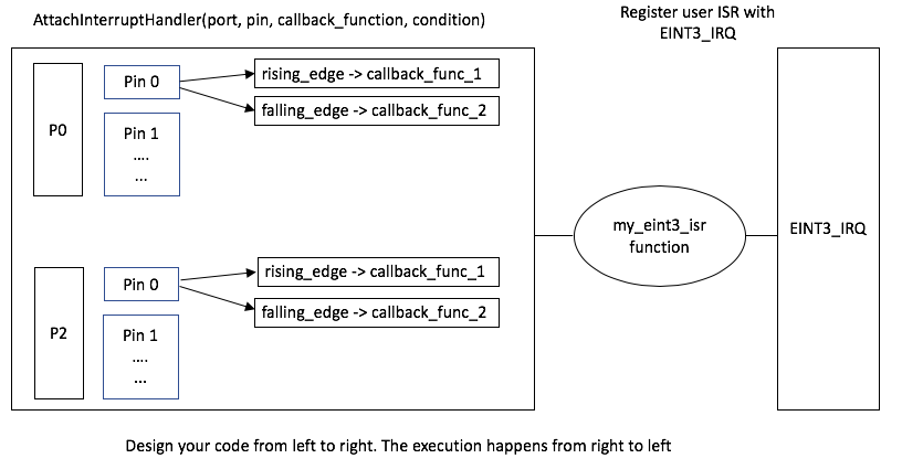
Part 1: Extend the LabGPIO driver
You are designing a library that will allow the programmer using your library to be able to "attach" a function callback to any and each pin on port 0 or port 2.
- Add and implement ALL class methods.
- All methods must function work as expected by their comment description.
#pragma once
// Gives you access to
#include "L0_LowLevel/interrupts.hpp"
class LabGPIO
{
public:
enum class Edge
{
kNone = 0,
kRising,
kFalling,
kBoth
};
static constexpr size_t kPorts = 2;
static constexpr size_t kPins = 32;
// This handler should place a function pointer within the lookup table for
// the GpioInterruptHandler() to find.
//
// @param isr - function to run when the interrupt event occurs.
// @param edge - condition for the interrupt to occur on.
void AttachInterruptHandler(IsrPointer isr, Edge edge);
// Register GPIO_IRQn here
static void EnableInterrupts();
private:
// Statically allocated a lookup table matrix here of function pointers
// to avoid dynamic allocation.
//
// Upon AttachInterruptHandler(), you will store the user's function callback
// in this matrix.
//
// Upon the GPIO interrupt, you will use this matrix to find and invoke the
// appropriate callback.
//
// Initialize everything to nullptr.
static IsrPointer pin_isr_map[kPorts][kPins] = { nullptr };
// This function is invoked by NVIC via the GPIO peripheral asynchronously.
// This ISR should do the following:
// 1) Find the Port and Pin that caused the interrupt via the IO0IntStatF,
// IO0IntStatR, IO2IntStatF, and IO2IntStatR registers.
// 2) Lookup and invoke the user's registered callback.
//
// VERY IMPORTANT!
// - Be sure to clear the interrupt flag that caused this interrupt, or this
// function will be called repetitively and lock your system.
// - NOTE that your code needs to be able to handle two GPIO interrupts
// occurring at the same time.
static void GpioInterruptHandler();
};
// ...
int main(void)
{
// This is just an example, use which ever pins and ports you like
Gpio gpio(2, 3);
gpio.EnableInterrupts();
while(true)
{
continue;
}
return 0;
}Code Block 2. GPIO Interrupt Driver Template Class
Requirements
- Should be able to specify a callback function for any port/pin for an exposed GPIO given a rising, falling, or both condition.
- We may ask you to change which port and pin causes a particular callback to be executed in your code and then recompile and re-flash your board to and prove it works with any port 0 or port 2 pin.
- You will need to use two external switches for this lab.
Note that printing 4 chars inside an ISR can take 1ms, and this is an eternity for the processor and should never be done, unless other than debug.
What to turn in:
- Place all relevant source files within a .pdf file.
- Turn in the screenshots of terminal output.
Lab Assignment: ADC + PWM
Objective
Implement an ADC driver, implement a PWM driver, and design and implement an embedded application, which uses both drivers.
This lab will utilize:
- ADC Driver
- PWM Driver
- FreeRTOS Tasks
- A potentiometer
- An RGB LED
Assignment
Part 0: Implement basic ADC Driver and read Light Sensor Values
- Channel 2 (Pin P0.25) already has Light Sensor connected to it.
- Create just 1 task which reads the Light sensor value and prints it periodically.
- While the task is running cover the light sensor and your task should print values <50.
- Use the flash light on your phone on the light sensor and your task should print values >3500.
void light_sensor_print_task(void *p)
{
/*
* 1) Initial ADC setup (Power, clkselect, pinselect, clkdivider)
* 2) Select ADC channel 2
* 3) Enable burst mode
*/
while(1) {
uint16_t ls_val = adc_read_channel(2);
printf("Light Sensor value is %d\n", ls_val);
delay_ms(100);
}
}Part 1: Implement an ADC Driver
Using the following header file,
- Implement adcDriver.cpp such that it implements all the methods in adcDriver.h below.
- Every method must accomplish its task as indicated in the comments.
- You may add any other methods to enhance the functionality of this driver.
- It is recommended that you test your ADC driver with ADC_PIN_0_25 because it is connected to the analog light sensor and this is probably the easiest way to test your driver.
For proper operation of the SJOne board, do NOT configure any pins as ADC except for 0.26, 1.30, 1.31
While in burst mode, do not wait for the "DONE" bit to get set.
#include <stdio.h>
#include "io.hpp"
class LabAdc
{
public:
enum Pin
{
k0_25, // AD0.2 <-- Light Sensor -->
k0_26, // AD0.3
k1_30, // AD0.4
k1_31, // AD0.5
/* These ADC channels are compromised on the SJ-One,
* hence you do not need to support them
*/
// k0_23 = 0, // AD0.0
// k0_24, // AD0.1
// k0_3, // AD0.6
// k0_2 // AD0.7
};
// Nothing needs to be done within the default constructor
LabAdc();
/**
* 1) Powers up ADC peripheral
* 2) Set peripheral clock
* 2) Enable ADC
* 3) Select ADC channels
* 4) Enable burst mode
*/
void AdcInitBurstMode();
/**
* 1) Selects ADC functionality of any of the ADC pins that are ADC capable
*
* @param pin is the LabAdc::Pin enumeration of the desired pin.
*
* WARNING: For proper operation of the SJOne board, do NOT configure any pins
* as ADC except for 0.26, 1.31, 1.30
*/
void AdcSelectPin(Pin pin);
/**
* 1) Returns the voltage reading of the 12bit register of a given ADC channel
* You have to convert the ADC raw value to the voltage value
* @param channel is the number (0 through 7) of the desired ADC channel.
*/
float ReadAdcVoltageByChannel(uint8_t channel);
};Part 2: Implement a PWM Driver
Using the following header file,
- Implement pwmDriver.cpp such that it implements all the methods in pwmDriver.h below.
- Every method must accomplish its task as indicated in the comments.
- You may add any other methods to enhance the functionality of this driver.
- It may be best to test the PWM driver by using a logic analyzer
#include <stdint.h>
class LabPwm
{
public:
enum Pin
{
k2_0, // PWM1.1
k2_1, // PWM1.2
k2_2, // PWM1.3
k2_3, // PWM1.4
k2_4, // PWM1.5
k2_5, // PWM1.6
};
/// Nothing needs to be done within the default constructor
LabPwm() {}
/**
* 1) Select PWM functionality on all PWM-able pins.
*/
void PwmSelectAllPins();
/**
* 1) Select PWM functionality of pwm_pin_arg
*
* @param pwm_pin_arg is the PWM_PIN enumeration of the desired pin.
*/
void PwmSelectPin(PWM_PIN pwm_pin_arg);
/**
* Initialize your PWM peripherals. See the notes here:
* http://books.socialledge.com/books/embedded-drivers-real-time-operating-systems/page/pwm-%28pulse-width-modulation%29
*
* In general, you init the PWM peripheral, its frequency, and initialize your PWM channels and set them to 0% duty cycle
*
* @param frequency_Hz is the initial frequency in Hz.
*/
void PwmInitSingleEdgeMode(uint32_t frequency_Hz);
/**
* 1) Convert duty_cycle_percentage to the appropriate match register value (depends on current frequency)
* 2) Assign the above value to the appropriate MRn register (depends on pwm_pin_arg)
*
* @param pwm_pin_arg is the PWM_PIN enumeration of the desired pin.
* @param duty_cycle_percentage is the desired duty cycle percentage.
*/
void SetDutyCycle(PWM_PIN pwm_pin_arg, float duty_cycle_percentage);
/**
* Optional:
* 1) Convert frequency_Hz to the appropriate match register value
* 2) Assign the above value to MR0
*
* @param frequency_hz is the desired frequency of all pwm pins
*/
void SetFrequency(uint32_t frequency_Hz);
};Part 3: Application
In order to demonstrate that both drivers function, you are required to interface a potentiometer and an RGB LED to the SJOne board. The potentiometer ADC input shall control the duty cycle of the RGB LED pwm outputs. Note that an RGB LED has three input pins that you will connect to three different PWM output pins. You must use your own ADC and PWM drivers, as well as your own FreeRTOS task.
Extra credit can be earned with an interesting/cool/creative RGB output.
Requirements
- Using your own ADC Driver, read input voltage from a potentiometer
- Print the voltage reading every 1s.
- Using your own PWM Driver, drive an RGB LED.
- Print the duty cycle of all three RGB pins every 1s.
- The PWM output to the RGB LED must be dependent on the ADC input from the potentiometer.
- By varying the potentiometer, you should be able to see changes in the color of the RGB Led.
You don't need a periodic task for the PWM to work. Initialize the driver, set period and duty cycle. PWM will start generating pulses immediately. You can vary the duty cycle of PWM inside the ADC task.
Lab Assignment: Device Interfacing w/ SPI + Data Structures
To learn how to create a single dynamic thread-safe driver for Synchronous Serial Port and to communicate with an external SPI Flash device.
This lab will utilize:
- Mutexes
- Enumerations
- Bit field and structure mapping
Assignment
Part 0: Simple SPI driver
This part is just for you to get started. After you get something functional, you need to move on to Part1 to elaborate your code. Thus this code is not something you should turn in. Also, before you go further, you should first read through the SPI flash datasheet to understand what you will try to communicate with.
This is your first step to completing the assignment. Get the code below to work and validate that you are able to read the SPI flash memory's "signature" bytes and compare with the SPI flash datasheet to ensure that this is correct.
void spi_init(void)
{
/* Init the exact SPI config to talk to the SPI flash */
}
uint8_t spi_transfer(uint8_t out)
{
}
// WARNING: This is just a sample; you will have to fill in plenty of your own code per requirements
void read_sig(void)
{
uint8_t d[2];
// The simplest test is to try to read the signature of the Adesto flash and print it out
adesto_cs();
{
d[0] = spi_transfer(0xAA); // TODO: Find what to send to read Adesto flash signature
d[1] = spi_transfer(0xBB);
}
adesto_ds();
printf("Returned data: %x %x\n", d[0], d[1]);
}
void main(void)
{
spi_init();
read_sig();
}Code Block 1. Simple SPI test
Part 1: Elaborate SPI driver
Using the following class template
- Implement ALL class methods.
- All methods must function work as expected by their comment description.
class LabSpi
{
public:
enum FrameModes
{
/* Fill this out based on the datasheet. */
};
/**
* 1) Powers on SPPn peripheral
* 2) Set peripheral clock
* 3) Sets pins for specified peripheral to MOSI, MISO, and SCK
*
* @param data_size_select transfer size data width; To optimize the code, look for a pattern in the datasheet
* @param format is the code format for which synchronous serial protocol you want to use.
* @param divide is the how much to divide the clock for SSP; take care of error cases such as the value of 0, 1, and odd numbers
*
* @return true if initialization was successful
*/
bool initialize(uint8_t data_size_select, FrameModes format, uint8_t divide);
/**
* Transfers a byte via SSP to an external device using the SSP data register.
* This region must be protected by a mutex static to this class.
*
* @return received byte from external device via SSP data register.
*/
uint8_t transfer(uint8_t send);
LabSpi();
~LabSpi();
private:
};Code Block 2. SSP Driver Template Class
Part 2: SPI Flash Reader Application
Application is to retrieve the information from the SJOne board's SPI flash's and print the information about each bit (or field of bits) to STDOUT in a nicely formatted human understandable way. If the 7th bit of a status register has been set you cannot simply print that "bit 7 is set". If bit 7 is the busy bit, then print a sentence like, "SPI Flash is currently busy" or "SPI Flash is NOT busy."
Read the signature bits and output them every second -- vTaskDelay(1000) in the task loop.
WHEN setting the clock in the application, set the clock rate to something reasonable according to the specifications of the device.
Part 3: Mutex
Since multiple tasks may access the SPI device in parallel, we need to create a Mutex to guard from simultaneous access from multiple tasks. In your sample project, the SPI bus is interfaced to the SD card and the SPI flash, and the guards are implemented at diskio.c file so when you perform file I/O operations, there will never be contention between multiple tasks trying to use the SPI bus. Study the diskio.c file and make sure you understand its intent.
Assume that your chip signature reader task can be instantiated twice, as in, you will create two tasks that will read the signature and output the data repeatedly. Guard your tasks to ensure that they will not step on each other in the middle of the CS() to DS() transaction. In fact, if you want to do it right, you should use the API from spi_sem.h such that even if I am trying to read a file using the terminal command, it will not interrupt your read-signature transaction.
Requirements
- Write your own SSP1 driver: Initialize the pins, clock, and the SSP driver.
- Remember that the CS signal outside of the SSP driver, and it should just be a GPIO driver
-
Communicate to the Adesto flash and print out the following registers from the SPI FLASH (not the SSP peripheral)
- Manufacture ID (print 8-bit hex value)
- 16-bit Device ID (print 16-bit hex value)
-
16-bit status register
- Detailed description of each bit's status
- MUST create and use a bit field structure map for this register and use that to print the bit information
- Ensure that you have the mutex in place during the SPI transactions
- Capture Saleae logic analyzer screenshot during the chip signature read
What to turn in:
- Place everything inside of main file or include all relevant files.
- Turn in the screenshots of terminal output.
- Logic Analyzer Screenshots
- Decoded Waveform of SPI retrieving manufacture ID.
For the logic analyzer, you must not forget to include the CS gpio pin otherwise, the waveform will not decode properly.
SCE (Engr294) has many logic analyzers that you can loan (or borrow). Please align your work schedule to make sure you can go to SCE while it is open.
Extra Credit :
- Read page zero (first 512 bytes) using the API at spi_flash.h, and print the following:
- MUST create and use a structure mapping for the whole 512 byte page.
- All meaningful contents of the 4 partition table entries.
- MUST create and use a packed bit field structure for the partition table entries.
- Boot signature
- Use a terminal command to execute this application.
FAT Information
File System essentially consists of data structures used to manage all the files in a storage device. FAT File system uses a data structure called File Allocation Table(FAT) to organize and store information about the location of files in a partition. A partition with FATFS stores all metadata about the files and file systems in its first sector called Partition Boot Sector. Each partition in a storage disk has its own Boot Sector that also contains boot code if that partition is bootable. The information about all such partitions are located in table called Partition Table which is in first sector of disk named Master Boot Record.
Master Boot Record
The first 512 bytes (Page 0 of memory) of the flash contains a Master Boot Record (MBR) which has pointers to where the partitions are placed in the storage device.
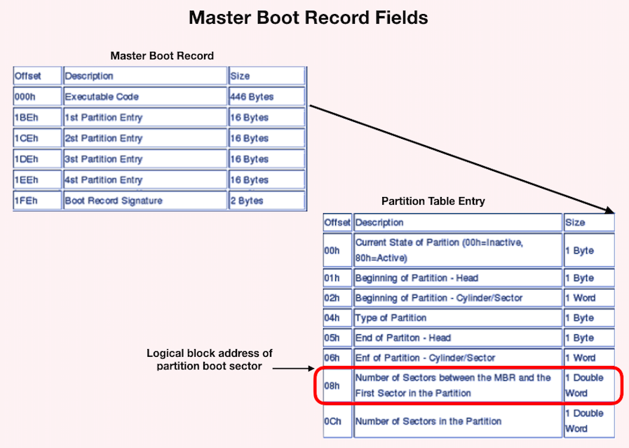
The first 446 bytes is the bootstrap code area. After that there is a partition table with four entries and then a boot signature (0x55AA). Each entry is 16 bytes long. To see the structure of the Master Boot Record: Sector layout and the structure of the entry can be found here Master Boot Record: Partition table entries.
In Summary, getting FAT File System information is a 2 step process where,
1. Read the Master Boot Record to obtain the location of the starting sector of FATFS partition which is its boot sector.
2. Read the Boot sector of the partition to obtain the FATFS information.
Additional Information:
One of the fields in the partition entry is "partition type". This should tell us what type of filesystem is resident on the partition. In our case it should be FAT12 (0x01). The last 8 bytes in the partition entry will tell us the Logical Block Address (LBA) of the first absolute sector in the partition and the total number of sectors in the partition. Essentially, we want to read the sector pointed to by this LBA for the FAT boot sector. That sector will give us the required information (no of clusters, total sectors, etc.. ).
SPI
Serial Peripheral Interface
What is SPI
SPI is a high-speed, full-duplex bus that uses a minimum of 3 wires to exchange data. The popularity of this bus rose when SD cards (and its variants ie: micro-sd) officially supported this bus according to the SD specifications. SPI allows microcontrollers to communicate with multiple slave devices.
SPI Bus Signals

Figure 1. SPI Signals
| MASTER Pin Name | SLAVE Pin Name | Pin Function |
| MOSI | SI | Master Out Slave In (driven by master), this pin is used to send sends data to the slave device. |
| MISO | SO | Master In Slave Out (driven by slave), this pin is used by the slave to send data to the master device. |
| SCLK | CLK | Serial Clock (driven by master), clock that signals when to read MISO and MOSI lines |
| CS | CS | Chip Select (driven by master), used to indicate to the slave that you want to talk to it and not another slave device. This will activate the slave's MISO line. MISO line is set to h-z if this is not asserted. MISO is set to high if this signal is asserted. |
| INT | Interrupt (Optional) (driven by slave), an interrupt signal to alert the master that the slave device wants to communicate. Not all devices have this. This is not always needed. This is not apart of the standard. |
The SCK signal can reach speed of 24Mhz and beyond, however, SD cards are usually limited to 24Mhz according to the specifications. Furthermore, any signal over 24Mhz on a PCB requires special design consideration to make sure it will not deteriorate, thus 24Mhz is the usual maximum. Furthermore, you need a CPU twice as fast as the speed you wish to run to support it. For example, to run at 24Mhz SPI, we need 48Mhz CPU or higher. Because each wire is driven directly (rather than open-collector), higher speeds can be attained compared to 400Khz I2C bus.
Multi-slave bus
Suppose that you wanted to interface a single SPI bus to three SD cards, the following will need to be done :
- Connect all MOSI, MISO, and SCK lines together
- Connect individual CS lines of three SD cards to SPI master (your processor)
It is also recommended to provide a weak pull-up resistor on each of the SPI wires otherwise some devices like an SD card may not work. 50K resistor should work, however, lower resistor value can achieve higher SPI speeds.

Figure 2. Typical SPI Bus (wikipedia SPI, user Cburnett)
As a warning, if your firmware selects more than one SPI slave chip select, and they both attempt to drive the MISO line, since those lines are totem-pole (push-pull), there will be bus contention and could possibly destroy both SPI devices.
The "CS" section of the SPI/SSP chapter describes the information if your microcontroller is going to be a slave on the SPI bus. Since your LPC micro is a master in reality, please do not confuse the CS pin for the SPI slave functionality. Even if the CS pin is actually used to CS the Adesto flash, it is just an ordinary GPIO and will not function as the one described in your SPI/SSP chapter.
Therefore, do not configure the "SSEL" in your PINSEL since that is reserved for the case when your micro is an SPI Slave. In your case, the same GPIO that has the "SSEL" capability is a simple GPIO to control the CS of the SPI Flash memory.
SPI Timing Diagram

Figure 3. SPI timing diagram
SPI has a few timing modes in which data is qualified on the rising or falling edge. In this case, and most, we qualify the MOSI and MISO signals on the rising edge. For a whole transaction to be qualified, the ~CS must be asserted. When the CS pin is pulled high (deasserted), the transaction is over and another transaction can be performed. This must be done for each transaction done by the master to the slave.
The SPI is labeled as SSP on LPC17xx datasheet due to historic reasons, and this chapter in the datasheet shows the software setup very well. After the SPI is initialized on the hardware pins, the next steps is to write an spi function that will exchange a byte. Note that if the master wants to receive data, it must send a data byte out to get a data byte back. The moment we write to the DR (data register) of the SPI peripheral, the MOSI will begin to send out the data. At the same time, the MISO will capture the data byte back to the same DR register. In other words, SPI bus is a forced full-duplex bus.
For completing two transactions successfully, there is a minimum delay required after you do a chip_deselect() and chip_select(). If they are issued back to back, then 2nd transaction will not give you the right data from the slave.
Why use SPI
Pros
-
High Speed:
- There is no standard speed limit for SPI beyond how fast a Single Ended Signal can propagate and how fast a SPI compatible device can react.
- In other words, how fast can you talk over a wire and how fast can a slave device read a clock signal.
-
Simple:
- Doesn't require special timing or a special state-machine to run. It doesn't really need a hardware peripheral either. It can be bit banged via GPIO.
-
Synchronous:
- This communication standard utilizes a clock to qualify signals.
-
Full-Duplex:
- Communication both ways. The slave to speak to the master at the same time that the master can speak to the slave device.
-
Multi-slave:
- You can talk to as many slaves as you have chip selects.
Cons
-
IO/Pin Count:
- IO count increases by one for each slave device you introduce, since each slave device needs a chip select.
- You also almost always need at least 4 wires for this communication protocol.
- There are some special cases that do not fit this but they are uncommon.
-
Master Only Control:
- Although the communication protocol can allow for full duplex communication, the only way for a slave device to be able to communicate with the master is if the master initiates communication.
- Slave can only speak when spoken to.
Software Driver

Preparation for the SPI driver
- Note that when we refer to SPI, we are referring to the SSP peripheral in the LPC user manual.
- SSP stands for Synchronous Serial Protocol and SPI is one of the synchronous serial protocols it can perform.
- Study the schematic, and take a note of which pins have the SSP1 or SPI#1 peripheral pin-out.
- Note this down or draw this out.
- Study and read the SSP1 LPC user manual chapter a few times
- Study the schematic, and locate the CS pin for the SPI flash attached to SSP1, then write a simple GPIO driver for this to select and deselect this pin
- Read the SPI flash datasheet that shows the SPI transactions for read/write, signature read etc.
- Rev.4 board has Adesto flash, and previous revisions have Atmel flash.
Multitasking Warnings: if your software runs multiple tasks, and these tasks can access SPI, care needs to be taken because if two CS signals are asserted at the same time, hardware damage will occur. This leads to the topic of using a mutex (semaphore) under FreeRTOS and you can read the FreeRTOS tutorial to learn more.
Set the clock rate to be below the specification of the SPI device you are interfacing.
Pin Control and Pin Function Selection (LPC40xx)
Objective
Learn about the selectable features of pins in the LPC40xx MCU, how to enable/disable these features and how to, select a pin's functionality.
Pin Features
The LPC40xx series chips have pins with the following features
see chapter Chapter 6: LPC408x/407x Pin configuration & Chapter 7: LPC408x/407x I/O configuration

Figure 1. I/O configurations Signals Highlighted (UM10562 LPC40xx Page 122)
- Open Drain Enable: Enabling this disables the high side MOSFET in of the totem pole configuration, making that pin an open drain.
-
Pin Modes (Only one or none of these can be active at once)
- Pull-Up Enable:Enabling this turns on the weak pull-down MOSFET in the ohmic region.
- Pull-Down Enable: Enabling this turns on the weak pull-down MOSFET in the ohmic region.
- Repeater Mode Enable: Enabling this, will activate the pull up or pull down resistor from the last.
- Enable Input Invert: Converts a pin configured as an input to active low.
- Enable Glitch Filter: Enables the 10nS glitch filter.
- Enable Analog Input: Disables schmitt trigger and enables voltage to pass through analog switch to analog input.
- There are actually more controls then this depending on the pin type you are using.

Figure 2. Type D IOCON registers (page 132)

Figure 3. Type A IOCON registers (page 138)

Figure 3. Type U IOCON registers. Only has a function (page 140)
Setting Pin Function
Every GPIO pin of the LPC40xx is capable of other alternative functionalities. Pin selection is the method by which a user is able to designate the functionality of any given pin. For example, GPIO Pin 0.0 can alternatively by used for CAN channel 1 receive, UART channel 3 transmit, and I2C channel 1 data line.

Figure 1B. I/O Pin Select Mux (from LPC2148, for illustration purposes only)
// Example of setting pin function using LPC40xx.h pointers
// Set as UART 0 Transmit U0_TXD
LPC_IOCON->P0_0 = (LPC_IOCON->P0_0 & ~0b111) | 0b100;
// Set as SSP0_SCK
LPC_IOCON->P0_15 = (LPC_IOCON->P0_15 & ~0b111) | 0b010;
For example, if one desires to configure pin 0.09 to enable a pull-up resistor and open drain mode, one must clear bits 18 & 19 of PINMODE0 register, and set bit 9 of register PINMODE_OD0.
// Using the memory address from the datasheet
*(0x4002C040) &= ~(0x3 << 18); // Clear bits 18 & 19
*(0x4002C068) |= (0x1 << 9); // Set bit 9
// Using LPC17xx.h pointers
LPC_PINCON->PINMODE0 &= ~(0x3 << 18); // Clear bits 18 & 19
LPC_PINCON->PINMODE_OD0 |= (0x1 << 9); // Set bit 9Structured Bit-fields Register Mapping
Please Review the Following
- Structures in C/C++: http://www.cplusplus.com/doc/tutorial/structures/
- Unions in C/C++: http://www.cplusplus.com/doc/tutorial/other_data_types/
Register Structure Mapping
Lets observe the status register for the ADXL362 accelerometer. The choice of this device is arbitrary.

Figure 1. ADXL362 Status Register
Normally, and more portably, to store information about the awake bit, you would do the following:
/* Get byte from accelerometer */
uint8_t status = getStatusByte();
/* Store 6th bit using a shift and mask */
bool awake = ((status >> 6) & 0b1);
// You can also do this (to guarantee the result to be true or false only, rather than 0 or (1 << 6) which is 64
bool awake = (status & (1 << 6)) ? true : false;
bool awake = !!(status & (1 << 6));
/* Now use the stored awake boolean */
if(awake)
{
doAThing();
}The above is fine, but it would be great to do this in a more elegant fashion. For example, the following:
/* Get a byte and cast it to our adlx_t structure */
adlx_t status = (adlx_t)getStatusByte();
/* Now retrieve the awake bit using the following syntax */
if(status.awake)
{
doAThing();
}To do something like this, you can define the adlx_t structure in the following way:
typedef struct __attribute__((packed))
{
uint8_t data_ready: 1;
uint8_t fifo_ready: 1;
uint8_t fifo_warning: 1;
uint8_t fifo_overrun: 1;
uint8_t activity: 1;
uint8_t : 1; /* Un-named padding, since I don't care about the inactivity signal */
uint8_t awake: 1;
uint8_t error: 1;
} adlx_t;The colon specifies the start of a bit field. The number after the colon is the length in bits that label will take up. The __attribute__((packed)) is a necessary compiler directive, specific to GCC which tells the compiler to make sure that the structure is packed together in the way that it is shown. It also tells the compiler to not rearrange it or expand it in order to make it more efficient to work with by the CPU.
NOTE: that the bit-field example and the shift and mask example are equivalent computationally. One is not necessarily more efficient the other. On one hand, you are writing the mask, in the other, the compiler does this for you.
Using Unions
Lets say we wanted to set the whole structure to zeros or a specific value, we can do this using unions.
typedef union
{
uint8_t byte;
struct
{
uint8_t data_ready: 1;
uint8_t fifo_ready: 1;
uint8_t fifo_warning: 1;
uint8_t fifo_overrun: 1;
uint8_t activity: 1;
uint8_t inactivity: 1;
uint8_t awake: 1;
uint8_t error: 1;
} __attribute__((packed));
} adlx_t;This allows the user to do the following:
/* Declare status variable */
adlx_t status;
/* Set whole bit field through the byte member */
status.byte = getStatusByte();
/* Use awake bit */
if (status.awake)
{
doSomething();
}
/* Clear bit field */
status.byte = 0;What about large data structures? For example, the ID3v1 metadata structure for MP3 files. This datastructure contains title name, artist and many other bits of information about the song to be played. It contains 128 bytes
| Field | Length | Description |
|---|---|---|
| header | 3 | "TAG" |
| title | 30 | 30 characters of the title |
| artist | 30 | 30 characters of the artist name |
| album | 30 | 30 characters of the album name |
| year | 4 | A four-digit year |
| comment | 28 | The comment. |
| zero-byte | 1 | If a track number is stored, this byte contains a binary 0. |
| track | 1 | The number of the track on the album, or 0. Invalid, if previous byte is not a binary 0. |
| genre | 1 | Index in a list of genres, or 255 |
This is not a bit field, but the same principles stand. This can be turned into a structure as well:
typedef union
{
uint8_t buffer[128];
struct
{
uint8_t header[3];
uint8_t title[30];
uint8_t artist[30];
uint8_t album[30];
uint8_t year[4];
uint8_t comment[28];
uint8_t zero;
uint8_t track;
uint8_t genre;
} __attribute__((packed));
} ID3v1_t;Now, it would take up 128 bytes of memory in to create one of these structures and we want to be conservative. To use use the structure properties, and reduce space usage you can utilize pointers and casting.
ID3v1_t mp3;
/* Some function to get the ID3v1 data */
dumpMP3DataIntoBuffer(&mp3.buffer[0]);
/* Compare string TAG with header member */
printf(" Title: %.30s\n", mp3.title);
printf("Artist: %.30s\n", mp3.artist);Using Macros
Using some casting techniques and macros you can do something like the following:
#define ADLX(reg) (*((adlx_t*)(®)))
uint8_t status = getStatusByte();
if (ADLX(status).awake)
{
doAThing();
}Dangers of Using Bit-fields
The above example that does not use bit-fields is quite portable, but bit-field mapping can be problematic depending on these factors
-
Endianess of your system: If a bit-field of a status register is little-endian and your processor is big-endian, the bits will be flipped.
- This link explains this further: http://opensourceforu.com/2015/03/be-cautious-while-using-bit-fields-for-programming/
- Structure of your struct: in gcc, using __attribute__((packed)) is very important, because the compiler may attempt to optimize that structure for speed, by expanding the members of the struct into 32-bits, or it may reorder the members and bit to make easier to do operations on. In these cases, the mapping will no longer work. This is something to consider when using this. This also typically depends on the compiler options for compiling.
- Mixing bit fields and members: See the link below on some issues that occurred when you mix bit-fields with variables.
SPI Lab
To learn how to create a single dynamic thread-safe driver for Synchronous Serial Port and to communicate with an external SPI Flash device.
This lab will utilize:
- Enumerations
- Bit field structure mapping
Assignment
Part 0: Simple SPI driver
This part is just for you to get started. After you get something functional, you need to move on to Part 1 to design your driver class. Also, before you go further, you should first read through the SPI flash datasheet to understand what you will try to communicate with.
This is your first step to completing the assignment. Get the code below to work and validate that you are able to read the SPI flash memory's "signature" bytes and compare with the SPI flash datasheet to ensure that this is correct.
void SpiInitialize(void)
{
// Initialize SSP peripheral
}
uint8_t SpiTransfer(uint8_t data_out)
{
// Send data_out and retrieve returned byte
}
// WARNING: This is just a sample; you will have to fill in plenty of your own code as per requirements
void ReadSignature()
{
uint8_t data[2];
// The simplest test is to try to read the signature of the Adesto flash and print it out
AdestoSelect();
{
// TODO: Find the correct commands you need to send to the Adesto flash device
// to retrieve its device signature.
data[0] = SpiTransfer(0xAA);
data[1] = SpiTransfer(0xBB);
}
AdestoDeselect();
printf("Returned data: %x %x\n", d[0], d[1]);
}
int main()
{
SpiInitialize();
ReadSignature();
}Code Block 1. Simple SPI test
Part 1: Elaborate SPI driver
Using the following class template
- Implement ALL class methods.
- All methods must function work as expected by their comment description.
class LabSpi
{
public:
enum FrameModes
{
/* Fill this out based on the datasheet. */
};
/**
* 1) Powers on SPPn peripheral
* 2) Set peripheral clock
* 3) Sets pins for specified peripheral to MOSI, MISO, and SCK
*
* @param data_size_select transfer size data width; To optimize the code, look for a pattern in the datasheet
* @param format is the code format for which synchronous serial protocol you want to use.
* @param divide is the how much to divide the clock for SSP; take care of error cases such as the value of 0, 1, and odd numbers
*
* @return true if initialization was successful
*/
bool Initialize(uint8_t data_size_select, FrameModes format, uint8_t divide);
/**
* Transfers a byte via SSP to an external device using the SSP data register.
* This region must be protected by a mutex static to this class.
*
* @return received byte from external device via SSP data register.
*/
uint8_t Transfer(uint8_t send);
private:
// Fill in as needed
};Code Block 2. SSP Driver Template Class
Part 2: SPI Flash Reader Application
Application is to retrieve the information from the SJOne board's SPI flash's and print the information about each bit (or field of bits) to STDOUT in a nicely formatted human understandable way. If the 7th bit of a status register has been set you cannot simply print that "bit 7 is set". If bit 7 is the busy bit, then print a sentence like, "SPI Flash is currently busy" or "SPI Flash is NOT busy."
Read the signature bits and output them every second. Use the #include "utility/time.hpp" file's Delay(1000); in the task loop.
WHEN setting the clock in the application, set the clock rate to something reasonable according to the specifications of the device. 1 Mhz and below should be fine.
Requirements
- Write your own SSP2 driver: Initialize the pins, clock, and the SSP driver.
- Remember that the CS signal outside of the SSP driver, and it should just be a GPIO driver
-
Communicate to the Adesto flash and print out the following registers from the SPI FLASH (not the SSP peripheral)
- Manufacture ID (print 8-bit hex value)
- 16-bit Device ID (print 16-bit hex value)
-
16-bit status register
- Detailed description of each bit's status
- MUST create and use a bit field structure map for this register and use that to print the bit information description.
- Capture the following information from Saleae logic analyzer:
- Complete waveform of command sent via MOSI and data retrieved via MISO from slave device along with chip select, and serial clock signals.
- A screenshot of the Decoded Protocol section (on the lower right) including
- manufacture id
- 16-bit device id
What to turn in:
- Place everything inside of main file or include all relevant files.
- Turn in the screenshots of terminal output.
- Logic Analyzer Screenshots
- Decoded waveform of SPI retrieving manufacture ID.
For the logic analyzer, you must not forget to include the CS gpio pin otherwise, the waveform will not decode properly.
SCE (Engr294) has many logic analyzers that you can loan (or borrow). Please align your work schedule to make sure you can go to SCE while it is open.
Extra Credit
- Write your group name along with the names of your group members to the SPI flash memory at address zero
- Be able to read back the names in that section of flash memory.
UART
UART (Universal Asynchronous Receiver-Transmitter)
Objective
The objective of this lesson is to understand UART, and use two boards and setup UART communication between them.
UART

Figure 1. UART connection between two devices.
For Universal Asynchronous Receiver Transmitter. There is one wire for transmitting data (TX), and one wire to receive data (RX).
BAUD Rate
A common parameter is the baud rate known as "bps" which stands for bits per second. If a transmitter is configured with 9600bps, then the receiver must be listening on the other end at the same speed.
UART Frame
UART is a serial communication, so bits must travel on a single wire. If you wish to send a 8-bit byte (uint8_t) over UART, the byte is enclosed within a start and a stop bit. To send a byte, it would require 2-bits of overhead; this 10-bit of information is called a UART frame. Let's take a look at how the character 'A' is sent over UART. In ASCII table, the character 'A' has the value of 65, which in binary is: 0100_0001. If you inform your UART hardware that you wish to send this data at 9600bps, here is how the frame would appear on an oscilloscope :

Figure 2. UART Frame sending letter 'A'
UART Ports
Benefits
- Hardware complexity is low.
- No clock signal needed
- Has a parity bit to allow for error checking
- As this is one to one connection between two devices, device addressing is not required.
Drawbacks
- The size of the data frame is limited to a maximum of 8 bits (some micros may support non-standard data bits)
- Doesn’t support multiple slave or multiple master systems
- The baud rates of each UART must be within 10% (or lower, depending on device tolerance) of each other
Hardware Design

Figure 3. Simplified UART peripheral design for the STM32F429. SCLK is used for USART.
WARNING: The above is missing a common ground connection
Software Driver
The UART chapter on LPC17xx has a really good summary page on how to write a UART driver.
Read the register description of each UART register to understand how to write a driver.
Memory Shadowing in UART driver

Figure 4. Memory Shadowing using DLAB Bit Register
In figure 4, you will see that registers RBR/THR and DLM have the same address 0x4000C000. These registers are shadowed using the DLAB control bit. Setting DLAB bit to 1 allows the user to manipulate DLL and DLM, and clearing DLAB to 0 will allow you to manipulate the THR and RBR registers.
The reason that the DLL register shares the same memory address as the RBR/THR may be historic. My guess is that it was intentionally hidden such that a user cannot accidentally modify the DLL register. Even if this case is not very significant present day, the manufacturer is probably using the same UART verilog code from many decades ago.
Control Space Divergence (CSD) in UART driver
In figure 4, you will see that register RBR and THR have the same address 0x4000C000. But also notice that access to each respective register is only from read or write operations. For example, if you read from memory location 0x4000C000, you will get the information from receive buffer and if you write to memory location 0x4000C000, you will write to a separate register which the transmit holding register. We call this Control Space Diverence since access of two separate registers or devices is done on a single address using the read/write control signal is used to multiplex between them. That address is considered to be Control Space Diverent. Typically, the control space aligns with its respective memory or io space.
Note that Control Space Divergence does not have a name outside of this course. It is Khalil Estell's phrase for this phenomenon. (Its my word... mine!)
BAUD Rate Formula

Figure 5. Baud rate formula
To set the baud rate you will need to manipulate the DLM and DLL registers. Notice the 256*UnDLM in the equation. That is merely another way to write the following (DLM << 8). Shifting a number is akin to multiplying it by 2 to the power of the number of shifts. DLM and DLL are the lower and higher 8-bits of a 16 bit number that divides the UART baudrate clock. DivAddVal and MulVal are used to fine tune the BAUD rate, but for this class, you can simply get "close enough" and ignore these values. Take these into consideration when you need an extremely close baudrate.
Advanced Design
If you used 9600bps, and sent 1000 characters, your processor would basically enter a "busy-wait" loop and spend 1040ms to send 1000 bytes of data. You can enhance this behavior by allowing your uart send function to enter data to a queue, and return immediately, and you can use the THRE or "Transmitter Holding Register Empty" interrupt indicator to remove your busy-wait loop while you wait for a character to be sent.
FreeRTOS & Tasks
Introduction to FreeRTOS
Objective
To introduce what, why, when, and how to use Real Time Operating Systems (RTOS) as well as get you
started using it with the SJSU-Dev environment.
I would like to note that this page is mostly an aggregation of information from Wikipedia and the FreeRTOS
website.
What is an OS?
Operating system (OS) is system software that manages computer hardware and software resources and provides common services for computer programs. - Wikipedia
Operating systems like Linux or Windows
They have services to make communicating with Networking devices and files systems possible without having
to understand how the hardware works. Operating systems may also have a means to multi-tasking by allow
multiple processes to share the CPU at a time. They may also have means for allowing processes to
communicate together.
What is an RTOS?
An RTOS is an operating system that meant for real time applications. They typically have fewer services such
as the following:
- Parallel Task Scheduler
- Task communication (Queues or Mailboxes)
- Task synchronization (Semaphores)
Why use an RTOS?
You do not need to use an RTOS to write good embedded software. At some point
though, as your application grows in size or complexity, the services of an RTOS might
become beneficial for one or more of the reasons listed below. These are not absolutes,
but opinion. As with everything else, selecting the right tools for the job in hand is an
important first step in any project.
In brief:
- Abstract out timing information
The real time scheduler is effectively a piece of code that allows you to specify the
timing characteristics of your application - permitting greatly simplified, smaller (and
therefore easier to understand) application code.
- Maintainability/Extensibility
Not having the timing information within your code allows for greater maintainability
and extensibility as there will be fewer interdependencies between your software
modules. Changing one module should not effect the temporal behavior of another
module (depending on the prioritization of your tasks). The software will also be less
susceptible to changes in the hardware. For example, code can be written such that it
is temporally unaffected by a change in the processor frequency (within reasonable
limits).
- Modularity
Organizing your application as a set of autonomous tasks permits more effective
modularity. Tasks should be loosely coupled and functionally cohesive units that within
themselves execute in a sequential manner. For example, there will be no need to
break functions up into mini state machines to prevent them taking too long to execute
to completion.
- Cleaner interfaces
Well defined inter task communication interfaces facilitates design and team
development.
- Easier testing (in some cases)
Task interfaces can be exercised without the need to add instrumentation that may
have changed the behavior of the module under test.
- Code reuse
Greater modularity and less module interdependencies facilitates code reuse across
projects. The tasks themselves facilitate code reuse within a project. For an example
of the latter, consider an application that receives connections from a TCP/IP stack -
the same task code can be spawned to handle each connection - one task per
connection.
- Improved efficiency?
Using FreeRTOS permits a task to block on events - be they temporal or external to
the system. This means that no time is wasted polling or checking timers when there
are actually no events that require processing. This can result in huge savings in
processor utilization. Code only executes when it needs to. Counter to that however is
the need to run the RTOS tick and the time taken to switch between tasks. Whether
the saving outweighs the overhead or vice versa is dependent of the application. Most
applications will run some form of tick anyway, so making use of this with a tick hook
function removes any additional overhead.
- Idle time
It is easy to measure the processor loading when using FreeRTOS.org. Whenever the
idle task is running you know that the processor has nothing else to do. The idle task
also provides a very simple and automatic method of placing the processor into a low
power mode.
- Flexible interrupt handling
Deferring the processing triggered by an interrupt to the task level permits the interrupt
handler itself to be very short - and for interrupts to remain enabled while the task level
processing completes. Also, processing at the task level permits flexible prioritization -
more so than might be achievable by using the priority assigned to each peripheral by
the hardware itself (depending on the architecture being used).
- Mixed processing requirements
Simple design patterns can be used to achieve a mix of periodic, continuous and
event driven processing within your application. In addition, hard and soft real time
requirements can be met though the use of interrupt and task prioritisation.
- Easier control over peripherals
Gatekeeper tasks facilitate serialization of access to peripherals - and provide a good
mutual exclusion mechanism.
- Etcetera
- FreeRTOS Website (https://www.freertos.org/FAQWhat.html)
Design Scenario
Building a controllable assembly conveyor belt
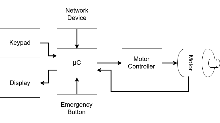
Think about the following system. Reasonable complex, right?
Without a scheduler
✓ Small code size.
✓ No reliance on third party source code.
✓ No RTOS RAM, ROM or processing overhead.
✗ Difficult to cater for complex timing requirements.
✗ Does not scale well without a large increase in complexity.
✗ Timing hard to evaluate or maintain due to the inter-dependencies between the different functions.
With a scheduler
✓ Simple, segmented, flexible, maintainable design with few inter-dependencies.
✓ Processor utilization is automatically switched from task to task on a most urgent need basis with no
explicit action required within the application source code.
✓ The event driven structure ensures that no CPU time is wasted polling for events that have not occurred.
Processing is only performed when there is work needing to be done.
* Power consumption can be reduced if the idle task places the processor into power save (sleep) mode,
but may also be wasted as the tick interrupt will sometimes wake the processor unnecessarily.
* The kernel functionality will use processing resources. The extent of this will depend on the chosen
kernel tick frequency.
✗ This solution requires a lot of tasks, each of which require their own stack, and many of which require a
queue on which events can be received. This solution therefore uses a lot of RAM.
✗ Frequent context switching between tasks of the same priority will waste processor cycles.
FreeRTOS Tasks
What is an FreeRTOS Task?
A FreeRTOS task is a function that is added to the FreeRTOS scheduler using the xCreateTask() API call.
A task will have the following:
- A Priority level
- Memory allocation
- Singular input parameter (optional)
- A name
- A handler (optional): A data structure that can be used to reference the task later.
A FreeRTOS task declaration and definition looks like the following:
void vTaskCode( void * pvParameters )
{
/* Grab Parameter */
uint32_t c = (uint32_t)(pvParameters);
/* Define Constants Here */
const uint32_t COUNT_INCREMENT = 20;
/* Define Local Variables */
uint32_t counter = 0;
/* Initialization Code */
initTIMER();
/* Code Loop */
while(1)
{
/* Insert Loop Code */
}
/* Only necessary if above loop has a condition */
xTaskDelete(NULL);
}Rules for an RTOS Task
- The highest priority ready tasks ALWAYS runs
- If two or more have equal priority, then they are time sliced
- Low priority tasks only get CPU allocation when:
- All higher priority tasks are sleeping, blocked, or suspended
- Tasks can sleep in various ways, a few are the following:
- Explicit "task sleep" using API call vTaskDelay();
- Sleeping on a semaphore
- Sleeping on an empty queue (reading)
- Sleeping on a full queue (writing)
Adding a Task to the Scheduler and Starting the Scheduler
The following code example shows how to use xTaskCreate() and how to start the scheduler using vTaskStartScheduler()
int main(int argc, char const *argv[])
{
//// You may need to change this value.
const uint32_t STACK_SIZE = 128;
xReturned = xTaskCreate(
vTaskCode, /* Function that implements the task. */
"NAME", /* Text name for the task. */
STACK_SIZE, /* Stack size in words, not bytes. */
( void * ) 1, /* Parameter passed into the task. */
tskIDLE_PRIORITY,/* Priority at which the task is created. */
&xHandle ); /* Used to pass out the created task's handle. */
/* Start Scheduler */
vTaskStartScheduler();
return 0;
}Task Priorities
High Priority and Low Priority tasks

In the above situation, the high priority task task never sleeps, so it is always running. In this situation where the low priority task never gets CPU time, we consider that task to be starved.
Tasks of the same priority
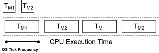
In the above situation, the two tasks have the same priority, thus they share the CPU. The time each task is allowed to run depends on the OS tick frequency. The OS Tick Frequency is the frequency that the FreeRTOS scheduler is called in order to decide which task should run next. The OS Tick is a hardware interrupt that calls the RTOS scheduler. Such a call to the scheduler is called a preemptive context switch.
Context Switching
When the RTOS scheduler switches from one task to another task, this is called a Context Switch.
What needs to be stored for a Context switch to happen
In order for a task, or really any executable, to run, the following need to exist and be accessible and storable:
-
Program Counter (PC)
- This holds the position for which line in your executable the CPU is currently executing.
- Adding to it moves you one more instruction.
- Changing it jumps you to another section of code.
-
Stack Pointer (SP)
- This register holds the current position of the call stack, with regard to the currently executing program. The stack holds information such as local variables for functions, return addresses and [sometimes] function return values.
-
General Purpose Registers
- These registers are to do computation.
-
In ARM:
- R0 - R15
-
In MIPS:
- $v0, $v1
- $a0 - $a3
- $t0 - $t7
- $s0 - $s7
- $t8 - $t9
-
Intel 8086
- AX
- BX
- CX
- DX
- SI
- DI
- BP
-
In ARM:
- These registers are to do computation.
How does Preemptive Context Switch work?
- A hardware timer interrupt or repetitive interrupt is required for this preemptive context switch.
- This is independent from an RTOS
- Typically 1ms or 10ms
- The OS needs hardware capability to have a chance to STOP synchronous software flow and enter the OS “tick” interrupt.
- This is called the "Operating System Kernel Interrupt"
- We will refer to this as the OS Tick ISR (interrupt service routine)
- Timer interrupt calls RTOS Scheduler
- RTOS will store the previous PC, SP, and registers for that task.
- Scheduler picks the highest priority task that is ready to run.
- Scheduler places that task's PC, SP, and registers into the CPU.
- Scheduler interrupt returns, and the newly chosen task runs as if it never stopped.
NOTE: Context switching takes time. The reason why most OS ticks are 1ms to 10ms, because any shorter means that there is less time for your code to run. If a context switch takes 100uS to do, then with a OS tick of 1ms, your code can only run for 900uS. If an OS Tick is only 150uS, then your code may only have enough time to run a few instructions. You spend more CPU time context switching then you do performing actual work.
Queues
RTOS Queues
There are standard queues, or <vector> in C++, but RTOS queues should almost always be used in your application because they are thread-safe (no race conditions with multiple tasks), and they co-operate with your RTOS to schedule the tasks. For instance, your task could optionally sleep while receiving data if the queue is empty, or it can sleep while sending the data if the queue is full.
Queues vs. Semaphore for "Signalling"
Semaphores may be used to "signal" between two contexts (tasks or interrupts), but they do not contain any payload. For example, for an application that captures a keystroke inside of an interrupt, it could "signal" the data processing task to awake upon the semaphore, however, there is no payload associated with it to identify what keystroke was input. With an RTOS queue, the data processing task can wake upon a payload and process a particular keystroke.
The data-gathering tasks can simply send the key-press detected to the queue, and the processing task can receive items from the queue, and perform the corresponding action. Moreover, if there are no items in the queue, the consumer task (the processing one) can sleep until data becomes available. You can see how this scheme lends itself well to having multiple ISRs queue up data for a task (or multiple tasks) to handle.
Example Queue usage for Tasks
After looking through the sample code below, you should then watch this video.
Let's study an example of two tasks communicating to each other over a queue.
QueueHandle_t q;
void producer(void *p)
{
int x = 0;
while (1) {
vTaskDelay(100);
xQueueSend(q, &x, 0); // TODO: Find out the significance of the parameters of xQueueSend()
++x;
}
}
void consumer(void *p)
{
while (1) {
// We do not need vTaskDelay() because this task will sleep for up to 100ms until there is an item in the queue
if (xQueueReceive(q, &x, 100)) {
printf("Got %i\n", x);
}
else {
puts("Timeout --> No data received");
}
}
}
void main(void)
{
// Queue handle is not valid until you create it
q = xQueueCreate(10, sizeof(int));
}
Example Queue usage with Interrupts
// Queue API is special if you are inside an ISR
void uart_rx_isr(void)
{
xQueueSendFromISR(q, &x, NULL); // TODO: Find out the significance of the parameters
}
void queue_rx_task(void *p)
{
int x;
// Receive is the usual receive because we are not inside an ISR
while (1) {
xQueueReceive(q, &x, portMAX_DELAY);
}
}
Additional Information
Queue Management (Amazon Docs)
Lab Assignment: UART
Objective
To learn how to communicate between two master devices using UART.
Assignment
This assignment will require two boards. The overall idea is to interface two boards using your UART driver. To test you can use a single board and perform a UART loopback (tie your own RX and TX wires together) in order to ensure that your driver is functional before trying to put two boards together.
Part 0: Get the simplest UART driver to function correctly
First, individually, get the simplest UART driver to work. Here is the rough skeleton:
// WARNING: Some of this is psuedocode, so you figure it out
void Uart2Interrupt()
{
// TODO: Queue your data and clear UART Rx interrupt
}
void InitializeUart2()
{
// Init PINSEL, baud rate, frame size, etc.
// Init UART Rx interrupt (TX interrupt is optional)
RegisterIsr(Uart2, Uart2Interrupt);
}
void Uart2Send(/* fill this out */)
{
// Send data via uart
}
void Uart2Recieve(/* fill this out */)
{
// Send data via uart
}
void vSendOverUartTask(void * pvParamater)
{
while (true)
{
Uart2Send(/* some data */);
vTaskDelay(1000);
}
}
void vRecieveByteOverUartTask(void * pvParamater)
{
while (true)
{
if (xQueueReceive(/* ... */, portMAX_DELAY))
{
printf("Got %c char from my UART... job is half done!");
}
}
}
void main(void)
{
InitializeUart2();
CreateTasks();
}HINT: You can test that your transmit and receive are working with only one SJOne board if you use a jumper to connect your UART TX and RX together. This is called a loopback test.
Part 1: Design UART driver
Using the following class template
- Design a UART driver as you have the previous drivers.
- Implement any functionality you deem useful for a general purpose UART driver.
- Document/comment each method and variable within the class template.
#pragma once
class LabUart
{
public:
// TODO: Fill in methods for Initialize(), Transmit(), Receive() etc.
//
// Optional: For the adventurous types, you may inherit from "CharDev" class
// to get a lot of functionality for free
private:
};Code Block 1. UART Driver Template Class
Part 2: Serial Application
For this application, one device will ask the other device to calculate the result of two numbers and an operation.

Figure 1
Think about it like this, using figure 1 as a guide:
- Device 1 sends a single digit '5', Device 2 receives single digit '5'
- Device 1 sends another single digit '7', device 2 receives single digit '7'
- Device 1 sends an operator '+', device 2 receives operator '+' and computes the result.
- Device 2 sends result back to device 1.
When the result is calculated, both the devices oled displays should show that resultant.
You MAY use the pre-written OLED driver for this lab.
Requirements
- Design UART driver to work with both UART2 and UART3
- UART receive should be interrupt driven
- When data arrives, store it to a FreeRTOS queue inside of the UART RX interrupt
- UART receive function should dequeue the data
- ALU application must be able to support the following operators
- + Addition
- - Subtraction
- * Multiplication
What to turn in:
- Submit all relevant files and files used (includes previous lab code used).
- Turn in any the screenshots of terminal output.
- Logic Analyzer Screenshots
- Waveform of device 1 UART TX sending a digits and operator to device 2.
- These can be in separate images if you can't fit everything in one image.
- Waveform of device 2 UART TX sending result back to device 1.
- Whole window screenshot with the Decoded Protocols (lower right hand side of window) clearly legible.
- Waveform of device 1 UART TX sending a digits and operator to device 2.
Extra Credit
Use the on-board buttons and OLED display as human interface devices (HID) and allow the user to punch in the numbers and operations in some way. Be creative about this.
If you are doing the extra credit, you may use the the L2/button driver.
I2C
I²C (Inter-Integrated Circuit)
What is I2C
I2C is pronounced "eye-squared see". It is also known as "TWI" because of the initial patent issues of this BUS. This is a popular, low throughput (100-1000Khz), half-duplex BUS that only uses two wires regardless of how many devices are on this BUS. Many sensors use this BUS because of its ease of adding to a system.

Figure x. of some devices connected up to an I2C bus
Pins of I2C
There are two pins for I2C:
- SCL: Serial clock pin
- SDA: Serial data pin
The clock line is usually controlled by the Master with the exception that the slave may pull it low to indicate to the master that it is not ready to send data.
The data line is bi-directional and is controlled by the Master while sending data, and by the slave when it sends data back after a repeat-start condition described below.
Open-Collector/Open-Drain BUS
I2C is an open-collector BUS, which means that no device shall have the capability of internally connecting either SDA or SCL wires to power source. The communication wires are instead connected to the power source through a "pull-up" resistor. When a device wants to communicate, it simply lets go of the wire for it to go back to logical "high" or "1" or it can connect it to ground to indicate logical "0". This achieves safe operation of the bus (no case of short circuit), even if a device incorrectly assumes control of the bus.

Figure x. Devices connected to I2C bus.

Figure x. I2C device pin output stage.
Pull-up resistor
Using a smaller pull-up can acheive higher speeds, but then each device must have the capability of sinking that much more current. For example, with a 5v BUS, and 1K pull-up, each device must be able to sink 5mA.
Why Use I2C
Pros
-
IO/Pin Count:
- 2 pins bus regardless of the number of devices.
-
Synchronous:
- No need for agreed timing before hand
-
Multi-Master
- Possible to have multiple masters on a I2C bus
-
Multi-slave:
- 7-bit address allows up to an absolute maximum of 119 devices (because 8 addresses are reserved)
- You can increase this number using I2C bus multiplexers
Cons
-
Slow Speed:
- Typical I2C devices have a maximum speed of 400kHz
- Some devices can sense speeds up to 1000kHz or more
-
Half-Duplex:
- Only one device can talk at a time
-
Complex State Machine:
- Requires a rather large and complex state machine in order to handle communication
-
Master Only Control:
- Only a master can drive the bus
- Exception to that rule is that a slave can stop stop the clock if it needs to hold the master in a wait state
-
Hardware Signal Protocol Overhead
- This protocol includes quite a few bits, not associated with data to handle routing and handshaking. This slows the bus throughput even further
Protocol Information
I2C was designed to be able to read and write memory on a slave device. The protocol may be complicated, but a typical "transaction" involving read or write of a register on a slave device is simple granted a "sunny-day scenario" in which no errors occur.
I2C at its foundation is about sending and receiving bytes, but there is a layer of unofficial protocol about how the bytes are interpreted. For instance, for an I2C write transaction, the master sends three bytes and 99% of the cases, they are interpreted like the following:
- Device Address
- Device Register
- Data
The code samples below illustrates I2C transaction split into functions, but this is the wrong way of writing an I2C driver. An I2C driver should be "transaction-based" and the entire transfer should be carried out using a state machine. The idea is to design your software to walk the I2C hardware through its state to complete an I2C transfer.
Signal Timing Diagram

Figure x. I2C communication timing diagram.
Write Transaction

Figure x. Master Transmit format
The master always initiates the transfer, and the device reading the data should always "ACK" the byte. For example, when the master sends the 8-bit address after the START condition, then the addressed slave should ACK the 9th bit (pull the line LOW). Likewise, when the master sends the first byte after the address, the slave should ACK that byte if it wishes to continue the transfer.
A typical I2C write is to be able to write a register or memory address on a slave device. Here are the steps:
- Master sends START condition followed by device address.
- Device that is addressed should then "ACK" using the 9th bit.
- Master sends device's "memory address" (1 or more bytes).
- Each byte should be ACK'd by the addressed slave.
- Master sends the data to write (1 or more bytes).
- Each byte should be ACK'd by the addressed slave.
- Master sends the STOP condition.
To maximize throughput and avoid having to send three I2C bytes for each slave memory write, the memory address is considered "starting address". If we continue to write data, we will end up writing data to M, M+1, M+2 etc.
The ideal way of writing an I2C driver is one that is able to carry out an entire transaction given by the function below.
NOTE: that the function only shows the different actions hardware should take to carry out the transaction, but your software will be a state machine.
void i2c_write_slave_reg(void)
{
// This will accomplish this:
// slave_addr[slave_reg] = data;
i2c_start();
i2c_write(slave_addr);
i2c_write(slave_reg); // This is "M" for "memory address of the slave"
i2c_write(data);
/* Optionaly write more data to slave_reg+1, slave_reg+2 etc. */
// i2c_write(data); /* M + 1 */
// i2c_write(data); /* M + 2 */
i2c_stop();
}Read Transaction
An I2C read is slightly more complex and involves more protocol to follow. What we have to do is switch from "write-mode" to "read-mode" by sending a repeat start, but this time with an ODD address. This transition provides the protocol to allow the slave device to start to control the data line. You can consider an I2C even address being "write-mode" and I2C odd address being "read-mode".
When the master enters the "read mode" after transmitting the read address after a repeat-start, the master begins to "ACK" each byte that the slave sends. When the master "NACKs", it is an indication to the slave that it doesn't want to read anymore bytes from the slave.
Again, the function shows what we want to accomplish. The actual driver should use state machine logic to carry-out the entire transaction.
void i2c_read_slave_reg(void)
{
i2c_start();
i2c_write(slave_addr);
i2c_write(slave_reg);
i2c_start(); // Repeat start
i2c_write(slave_addr | 0x01); // Odd address (last byte Master writes, then Slave begins to control the data line)
char data = i2c_read(0); // NACK last byte
i2c_stop();
}
void i2c_read_multiple_slave_reg(void)
{
i2c_start();
i2c_write(slave_addr);
i2c_write(slave_reg);
// This will accomplish this:
// d1 = slave_addr[slave_reg];
// d2 = slave_addr[slave_reg + 1];
// d3 = slave_addr[slave_reg + 2];
i2c_start();
i2c_write(slave_addr | 0x01);
char d1 = i2c_read(1); // ACK
char d2 = i2c_read(1); // ACK
char d3 = i2c_read(0); // NACK last byte
i2c_stop();
}I2C Slave State Machine Planning
Before you jump right into the assignment, do the following:
- Read and understand how an I2C master performs slave register read and write operation
- Look at existing code to see how the master operation handles the I2C state machine function.
- Next to each of the master state, determine which slave state is entered when the master enters its state
- Determine how your slave memory or registers will be read or written
In each of the states given in the diagrams below, your software should take the step, and the hardware will go to the next state granted that no errors occur. To implement this in your software, you should:
- Perform the planned action after observing the current state
- Clear the "SI" (state change) bit for HW to take the next step
- The HW will then take the next step, and trigger the interrupt when the step is complete
Master Write
In the diagram below, note that when the master sends the "R#", which is the register to write, then the slave state machine should save this data byte as it's INDEX location. Upon the next data byte, the indexed data byte should be written.
Stop here and do the following:
1. Check I2c::I2cHandler()
2. Compare the code to the state diagram below


Master Read
In the diagram below, the master will write the index location (the first data byte), and then perform a repeat start. After that, you should start returning your indexed data bytes.


I2C Slave Lab Assignment
Objective
Get hands on experience working with and understanding how I2C works by implementing an I2C slave device.
Assignment
- The I2C master driver is already implemented in SJSU-Dev2.
- Study the existing I2C code: i2c.hpp file and extend it to handler slave mode operation.
- Flashing the example project CommandLine on to the board (completely unmodified) and connect it to your 2nd Slave Board which will contain your i2c slave driver.
- On your master board, you can just use the
i2cterminal command to read and write to the I2C registers of a slave device. - See
helpfor the help about the command
- On your master board, you can just use the
Part 0: Read the I2C Chapter
IGNORE THE Software Implementation of the I2C chapter. It is not correct and does not match the proper information laid out in the state diagram and truth tables.
- Read over the I2C chapter and the various registers it contains. You may ignore the DMA registers. In order to grasp the amount of information in the chapter, you may need to read it multiple times.
- Draw out the state machine outlined in the chapter's state diagram and truth table for yourself.
Part 1: Get I2C Slave Interrupt to fire
In this Part 0 of this assignment, your objective is to simply to initialize your I2C slave to get its first state interrupt to fire.
- Add your
InitializeAsSlave()method - Add the slave address recognized state into your I2C slave driver and print a message when you hit this state inside the ISR.
- Connect this Master Board to the Slave Board by wire-wrapping the I2C SCL/SDA wires together.
- To test that your slave driver initialize is working, invoke
i2c discoveron the master board. Your slave board's address will appear.
When you connect the two boards to I2C There will be two of each sensor with the same address, which too is sort of okay. For example, the temperature sensor at the same address (from the 2 boards).
#include <cstdint>
#include <cstdio>
#include "L1_Drivers/i2c.hpp"
// Slave Board sample code reference
int main(void)
{
// Create I2c object (defaults to I2C2)
I2c i2c;
// Pick any address other than an existing ones on the board. Use `i2c discover` to see what those are.
const uint8_t slaveAddr = 0xC0;
// Our devices read/write buffer (This is the memory your master board will read/write)
volatile uint8_t buffer[256] = { 0 };
// I2C is already initialized before main(), so you will have to add initSlave() to i2c base class for your slave driver
i2c.InitializeSlave(slaveAddr, buffer, sizeof(buffer));
// I2C interrupt will (should) modify our buffer.
// So monitor the buffer, and print and/or light up LEDs
// ie: If buffer[0] == 0, then LED ON, else LED OFF
uint8_t prev = buffer[0];
while(true)
{
if (prev != buffer[0])
{
printf("buffer[0] changed from 0x%08X to 0x%08X by the other Master Board\n", prev, buffer[0]);
prev = buffer[0];
}
}
return 0;
}Part 2: Implement I2C slave behavior in I2CHandler
- Using the state machine diagrams in the datasheet before you begin, make sure you fully understand the slave states. The code you implement will need to follow the state machine guidelines exactly.
- Extend I2C state machine to handle I2C slave operations.
You may add printf statements to the I2C state machine code to identify what states you enter when the Master Board is trying to do an I2C transaction.
Requirements
See Canvas.
-
Extra Credit:
• Get multi byte read and write operation to work.• Do something creative with your slave board since you have essentially memory mapped the slave device over I2C. Maybe use buffer[0] to enable a blinking LED, and buffer[1] controls the blink frequency? You can do a lot more. Just blinking the LEDs is not enough.
FreeRTOS
FreeRTOS Primitives, Data structures, and inter-task communication
Binary Semaphore
Semaphores are used to signal/synchronize tasks as well as protect resources.
A binary semaphore can (and should) be used as a means of signaling a task. This signal can come from an interrupt service routine or from another task. A semaphore is an RTOS primitive and is guaranteed to be thread-safe.
Design Pattern
Wake Up On Semaphore
The idea here is to have a task that is waiting on a semaphore and when it is given by an ISR or an other task, this task unblocks, and runs its code. This results in a task that usually sleeping/blocked and not utilizing CPU time unless its been called upon. In FreeRTOS, there is a similar facility provided which is called 'deferred interrupt processing'. This could be used to signal an emergency shutdown procedure when a button is triggered, or to trigger a procedure when the state of the system reaches a fault condition. Sample code below:
/* Declare the instance of the semaphore but not that you have to still 'create' it which is done in the main() */
SemaphoreHandle_t xSemaphore;
void vWaitOnSemaphore( void * pvParameters )
{
while(1)
{
/* Wait forever until a the semaphore is sent/given */
if(xSemaphoreTake(xSemaphore, portMAX_DELAY))
{
printf("Semaphore taken\n");
/* Do more stuff below ... */
}
}
}
void vSemaphoreSupplier( void * pvParameters )
{
while(1)
{
if(checkButtonStatus())
{
xSemaphoreGive(xSemaphore);
}
/* Do more stuff ... */
}
}
int main()
{
/* Semaphore starts 'empty' when you create it */
xSemaphore = xSemaphoreCreateBinary();
/* Create the tasks */
const uint32_t STACK_SIZE_WORDS = 128;
xTaskCreate(vWaitOnSemaphore, "Waiter", STACK_SIZE_WORDS, NULL, tskIDLE_PRIORITY+1, NULL);
xTaskCreate(vSemaphoreSupplier, "Supplier", STACK_SIZE_WORDS, NULL, tskIDLE_PRIORITY+1, NULL);
/* Start Scheduler */
vTaskStartScheduler();
}Code Block 1. How to use Semaphores and use as a wake up pattern
Semaphore as a flag
The idea of this is to have a code loop that checks the semaphore periodically with the 'block time' of your choice. The task will only react when it notices that the semaphore flag has been given. When your task takes it, it will run an if statement block and continue its loop. Keep in mind this will consume your flag, so the consumer will loop back and check for the presence of the new flag in the following loop.
void vWaitOnSemaphore( void * pvParameters )
{
while(1)
{
/* Check the semaphore if it was set */
if(xSemaphoreTake(xSemaphore, 0))
{
printf("Got the Semaphore, consumed the flag indicator.");
/* Do stuff upon taking the semaphore successfully ... */
}
/* Do more stuff ... */
}
}Code Block 2. Semaphores as a consumable flag
Interrupt Signal from ISR
This is useful, because ISRs should be as short as possible as they interrupt the software or your RTOS tasks. In this case, the ISR can defer the work to a task, which means that the ISR runtime is short. This is important because when you enter an interrupt function, the interrupts are disabled during the ISRs execution. The priority of the task can be configured based on the importance of the task reacting to the semaphore.
You may not want to defer interrupt processing if the ISR is so critical that the time it takes to allow RTOS to run is too much. For example, a power failure interrupt.
void systemInterrupt()
{
xSemaphoreGiveFromISR(xSemaphore);
}
void vSystemInterruptTask(void * pvParameter)
{
while(1)
{
if(xSemaphoreTake(xSemaphore, portMAX_DELAY))
{
// Process the interrupt
}
}
}Code Block 3. Semaphore used within an ISR
NOTICE: The FromISR after the xSemaphoreGive API call? If you are making an RTOS API call from an ISR, you must use the FromISR variant of the API call. Undefined behavior otherwise like freezing the system.
Mutexes
Semaphores vs Mutexs
Semaphores and mutexes are nearly the same construct except that mutexes have the feature of priority inheritance, where in a low priority task can inheritate the priority of a task with greater priority if the higher priority task attempts to take a mutex that the low priority task possess.
Priority Inversion Using a Semaphore
Below is an illustration of the scenario where using a semaphore can cause priority inversion.
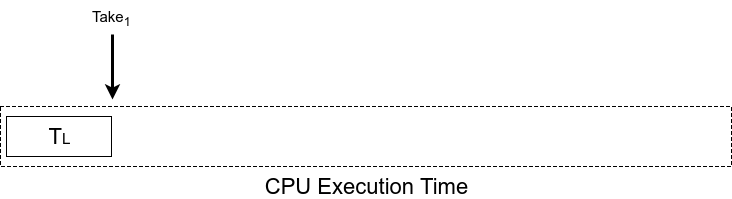
Figure 1. Low priority task is currently running and takes a semaphore.
.png)
Figure 2. OS Tick event occurs.
.png)
Figure 3. High priority task is ready to run and selected to run.
.png)
Figure 4. High priority task attempts to take semaphore and blocks.
.png)
Figure 5. Since high priority task is blocked, the next ready task that can run is the low priority task. The OS tick event occurs.
.png)
Figure 6. The OS tick event occurs, a middle priority task, that never sleeps is ready to run, it begins to run, high priority task is blocked on semaphore and low priority task is blocked by the middle priority task. This is priority inversion, where a medium priority task is running over a higher priority task.
Priority Inheritance using Mutex
Priority inheritance is the means of preventing priority inversion.
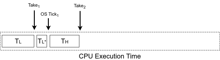
Figure 7. Moving a bit further, the high priority task attempts to take the Mutex
.png)
Figure 6. Low priority task inherates the highest priority of the task that attempts to take the mutex it posses.
.png)
Figure 7. OS Tick2 occurs, and medium priority task is ready, but the low priority task has inheritated a higher priority, thus it runs above the medium priority task.
.png)
Figure 7. Low priority task gives the mutex, low priority task de-inheritates its priority, and the high task immediately begins to run. It will run over the medium task.
.png)
Figure 7. At give2 high priority task releases the mutex and sleeps. Some time elapses, and then the medium task begins to run. No priority inversion occurs in this scenario, the RTOS rule of highest priority runs first is held.
Design Pattern
The design pattern for a mutex should be exclusively used as a protection token. Mutexes can be used in place of as semaphores but the addition work of priority inheritance will cause this approach to take longer and thus be less efficient than a semaphore.
// In main(), initialize your Mutex:
SemaphoreHandle_t spi_bus_lock = xSemaphoreCreateMutex();
void vTaskOne()
{
while(1) {
if(xSemaphoreGet(spi_bus_lock, 1000)) {
// Use Guarded Resource
// Give Semaphore back:
xSemaphoreGive(spi_bus_lock);
}
}
}
void vTaskTwo()
{
while(1) {
if(xSemaphoreGet(spi_bus_lock, 1000)) {
// Use Guarded Resource
// Give Semaphore back:
xSemaphoreGive(spi_bus_lock);
}
}
}
Queues
RTOS Queues
There are standard queues, or <vector> in C++, but RTOS queues should almost always be used in your application because they are thread-safe (no race conditions with multiple tasks), and they co-operate with your RTOS to schedule the tasks. For instance, your task could optionally sleep while receiving data if the queue is empty, or it can sleep while sending the data if the queue is full.
Queues vs. Semaphore for "Signalling"
Semaphores may be used to "signal" between two contexts (tasks or interrupts), but they do not contain any payload. For example, for an application that captures a keystroke inside of an interrupt, it could "signal" the data processing task to awake upon the semaphore, however, there is no payload associated with it to identify what keystroke was input. With an RTOS queue, the data processing task can wake upon a payload and process a particular keystroke.
The data-gathering tasks can simply send the key-press detected to the queue, and the processing task can receive items from the queue, and perform the corresponding action. Moreover, if there are no items in the queue, the consumer task (the processing one) can sleep until data becomes available. You can see how this scheme lends itself well to having multiple ISRs queue up data for a task (or multiple tasks) to handle.
Design Pattern
After looking through the sample code below, you should then watch this video.
Let's study an example of two tasks communicating to each other over a queue.
QueueHandle_t q;
void producer(void *p)
{
int value_put_sent_on_queue = 0;
while (1) {
vTaskDelay(100);
xQueueSend(q, &value_put_sent_on_queue, 0); // TODO: Find out the significance of the parameters of xQueueSend()
++value_put_sent_on_queue;
}
}
void consumer(void *p)
{
int variable_to_store_value_retreived_from_queue;
while (1) {
// We do not need vTaskDelay() because this task will sleep for up to 100ms until there is an item in the queue
if (xQueueReceive(q, &variable_to_store_value_retreived_from_queue, 100)) {
printf("Got %i\n", variable_to_store_value_retreived_from_queue);
}
else {
puts("Timeout --> No data received");
}
}
}
void main(void)
{
// Queue handle is not valid until you create it
q = xQueueCreate(10, sizeof(int));
}
Example Queue usage with Interrupts
// Queue API is special if you are inside an ISR
void uart_rx_isr(void)
{
xQueueSendFromISR(q, &x, NULL); // TODO: Find out the significance of the parameters
}
void queue_rx_task(void *p)
{
int x;
// Receive is the usual receive because we are not inside an ISR
while (1) {
xQueueReceive(q, &x, portMAX_DELAY);
}
}
Additional Information
Queue Management (Amazon Docs)
Task Suspension and Resumption
A freeRTOS task that is currently running can be suspended by another task or by its own task. A suspended task will not get any processing time from the micro-controller. Once suspended, it can only be resumed by another task.
API which can suspend a single task is:
void vTaskSuspend( TaskHandle_t xTaskToSuspend );Refer this link to explore more details on the API. https://www.freertos.org/a00130.html
API to suspend the scheduler is:
void vTaskSuspendAll( void );Refer this link to explore more details on the API. https://www.freertos.org/a00134.html
void vTaskResume( TaskHandle_t xTaskToResume );Refer this link to explore more details. https://www.freertos.org/a00131.html
BaseType_t xTaskResumeAll( void );Refer this link to explore more details. https://www.freertos.org/a00135.html
Although this may seem useful, do refrain from using these.
Many engineers will use task resume and suspend to control the flow of the system, but this is rarely done elegantly, and can result in weird behavior if abused.
Use these sparingly and only when all other options have been deemed nonoptimal and this is the most optimal solution.
Event Groups
Event group APIs can be used to monitor a set of tasks. A software watchdog in an embedded system can make use of event groups for a group of tasks and notify/alert the user if any of the task misbehaves.
Each task uses an event bit. After every successful iteration of the task, the bit can be set by the task to mark completion. The event bits are then checked in the watchdog task to see if all the tasks are running successfully. If any of the bits are not set, then watchdog task can alert about the task to the user.
Below are the APIs that can be used. Refer to each of the API to understand how to use them in your application.
- xEventGroupCreate
- xEventGroupCreateStatic
- xEventGroupWaitBits
- xEventGroupSetBits
- xEventGroupSetBitsFromISR
- xEventGroupClearBits
- xEventGroupClearBitsFromISR
- xEventGroupGetBits
- xEventGroupGetBitsFromISR
- xEventGroupSync
- vEventGroupDelete
Watchdogs
Please follow the steps precisely in order to complete the objectives of the assignment.
- Create a producer task that takes 1 temperature sensor value every 1ms.
- After collecting 100 samples (after 100ms), compute the average.
- Write average value every 100ms (avg. of 100 samples) to a sensor queue.
- Use medium priority for this task (see
util/rtos.hpp) - See
examples/Temperaturefor an example on how to use the temperature sensor driver.
- Create a consumer task that pulls the data off the sensor queue.
- Use infinite timeout value during queue receive API
- Open a file, sensor.txt, and append the data to an output file on the SD card.
- Save the data in this format:
printf("%i, %i\n", time, temperature); - Note that if you write and close a file every 100ms, it may be very inefficient, so try to come up with a better method such that the file is only written once a second or so ...
- Use medium priority for this task.
- At the end of the loop of each task, set a bit using FreeRTOS event group API.
- At the end of each loop of the tasks, set a bit using the
xEventGroupSetBits() - Task 1 should set bit 1, Task 2 should set bit 2 etc ...
- At the end of each loop of the tasks, set a bit using the
- Create a watchdog task that monitors the operation of the two tasks.
- Use high priority for this task.
- Wait 1 second for all of the task bits to be set. If there are two tasks, wait for bit1, and bit2 etc...
- If you fail to detect the bits are set, that means that the other tasks did not reach the end of the loop.
- In the event that a task failed to set its event group bit, append to a file, stuck.txt, with the information about which task is "stuck"
- Open the file, append the data, and close the stuck.txt file to flush out the data immediately.
- Create a terminal command to "suspend" and "resume" a task by name.
- "task suspend task1" should suspend a task named "task1"
- "task resume task2" should suspend a task named "task2"
- Use the
examples/Commandlineproject as an
- Run the system, and under normal operation, you will see a file being saved with sensor data values.
- Plot the file data in Excel to demonstrate the variation in the data.
- Make sure the data has some variation. This can be done by touching the top of the temperature sensor.
- Suspend the producer task. The watchdog task should display a message and save relevant info to the SD card.
- Let the system run for a while, and note down the CPU usage in your text file.
What you created is a "software watchdog". This means that in an event when a loop is stuck, or a task is frozen, you can save relevant information such that you can debug at a later time.
You may use any built in libraries for this lab assignment.
For File I/O refer examples/FileIO project
And the API documentation here: http://elm-chan.org/fsw/ff/00index_e.html
Extra Credit
Every sixty seconds, save the CPU usage info to a file named cpu.txt. See command "info" as a reference.
Coding Standards
Existing Code Structure
Remember that consistency is more important than standards. That means that you can make different decisions, but it is important to stay consistent. With that side, for better or worse, C code uses under_score_standard while C++ code usesCamelCase. This is an inconsistency that needs to be fixed because the developers realized that acronyms do not work well with camel case and this was realized too late.
Secondly, FreeRTOS follows significantly different coding standard. Please read more about it here, but the biggest hint is that the first letter, such as "v" in vTaskDelay means that it is a void return type.
Goals
- Easily reusable from common multi purpose functions and objects.
- Easily maintainable from consistent coding practices.
- Easily understood code from well described methods and self-documenting variables.
Code Structure
- DO NOT include unused headers in a source file
- ALWAYS use parenthesis arguments in any mathematical expression. Do not rely on operator precedence.
- ALWAYS Prioritize code maintainability over code complexity
- DO NOT use break statements except for in switch statements
- ALWAYS put curly braces must be on their own line
int32_t algorithm(int32_t a, int32_t b)
{
if(a < 0)
{
a = -a;
}
return (a + b);
}-
NEVER omit curly braces
- NEVER single line an if statement
int32_t algorithm(int32_t a, int32_t b)
{
if(a < 0) a = -a; /* NOT ALLOWED */
if(a < 0)
a = -a; /* NOR IS THIS ALLOWED */
if(a < 0) { a = -a; } /* REFRAIN FROM THIS AS WELL, MAKES DEBUGGING CODE LINES AMBIGUOUS */
return (a + b);
}- REFRAIN from functions that are more than 100 lines. Make code highly modular
- DO NOT have more than one exit (return statement) point from a function
/* BAD */
int32_t algorithm(int32_t a, int32_t b)
{
if(a < 25)
{
return 25;
}
else
{
return b;
}
}
/* GOOD */
int32_t algorithm(int32_t a, int32_t b)
{
int result;
if(a < 25)
{
result = 25;
}
else
{
result = b;
}
return result;
}-
ALWAYS Use spaces around all operators.
-
DO:
uint32_t counter = 5 + 2; -
DO NOT:
uint32_t counter=5+2;
-
DO:
- ALWAYS include a default case in a switch statements
-
ALWAYS Use 4 spaces for indentations
- Do not use tab characters in your source
- ALWAYS Separate logical blocks with one blank line
//Bad Example
uint8_t current[6];
//Good Example
const uint32_t NUM_DEVICES = 6;
uint8_t current[NUM_DEVICES];Memory
- REFRAIN from dynamically allocating memory
Variables (snake_case)
- REFRAIN from creating global variables.
-
ALWAYS put constants, enumerations, structures, objects/variables at the top of the scope
- For global variables that means the top of the file
- For local variables to a function, the top of a function
- ALWAYS use highly descriptive variable names
-
ALWAYS use snake_case for variable names
- Example:
uint32_t interrupt_counter = 0;
- Example:
Types (snake_case)
-
ALWAYS use
<stdint.h>integer types from:uint8_t,int8_t,uint16_t,int16_t,uint32_t,int32_t, etc -
ALWAYS use booleans from
stdbool.h. - NEVER use floats for calculations, use doubles instead. You may store floating point values as floats or doubles.
Macros (CAPS)
- Use of macros should be limited to preprocessor conditionals and that is it
- Any flags should be checked for as the following:
#if (MY_FEATURE)
- Any flags should be checked for as the following:
Inline Functions (CAPS)
- DO use this in place of Macro functions.
/* !!BAD!! */
#define HASH(letter) (uint8_t)(letter-'A')
/* GOOD */
inline uint8_t HASH(char letter)
{
return (uint8_t)(letter-'A');
}Constants (CAPS)
- ALWAYS use const or enumerations instead of "magic" numbers
- Use unit names in constants.
- Use constants to convert between units instead of hard coding the conversions.
const uint32_t MILLISECONDS = 1;
const uint32_t SECONDS = (1000 * MILLISECONDS);Functions (camelCase)
- ALWAYS use CamelCase for function names
- Attempt to make functions generic so it can be reused.
Classes/Structures/Objects (CapCamelCase)
-
Protected Section
- Member variables as private
-
Private Section
- Not used
-
Public Section
- Methods
- Setters and getter methods
- Declare constants within classes as static
- Constructors should not alter or modify hardware/registers.