LABS
- Lab: Queue
- LAB: Unit testing with mocks
- LAB: GPS and UART
- LAB: CAN bus
- LAB: CAN bus with DBC
- LAB: RC Car Infrastructure
- LAB: Geo Controller
Lab: Queue
Part 1
Write the unit-tests first, and then the implementation for the following header file:
#pragma once

#include <stdbool.h>
#include <stddef.h>
#include <stdint.h>

/* In this part, the queue memory is statically defined
 * and fixed at compile time for 100 uint8s
 */
typedef struct {
  uint8_t queue_memory[100];

  // TODO: Add more members as needed
} queue_s;

// This should initialize all members of queue_s
void queue__init(queue_s *queue);

/// @returns false if the queue is full
bool queue__push(queue_s *queue, uint8_t push_value);

/// @returns false if the queue was empty
bool queue__pop(queue_s *queue, uint8_t *pop_value);

size_t queue__get_item_count(const queue_s *queue);
Students often time create non optimal and incorrect implementation of a queue. Remember that a queue means FIFO data structure, which means oldest item pushed should be the first one out of the pop operation. Here are some unit tests that you are required to add to your test. This test will ensure that your implementation is correct.
void test_comprehensive(void) {
  const size_t max_queue_size = 100; // Change if needed

  for (size_t item = 0; item < max_queue_size; item++) {
    const uint8_t item_pushed = (uint8_t) item;
    TEST_ASSERT_TRUE(queue__push(&queue, item_pushed));
    TEST_ASSERT_EQUAL(item + 1, queue__get_item_count(&queue));
  }

  // Should not be able to push anymore
  TEST_ASSERT_FALSE(queue__push(&queue, 123));
  TEST_ASSERT_EQUAL(max_queue_size, queue__get_item_count(&queue));

  // Pull and verify the FIFO order
  for (size_t item = 0; item < max_queue_size; item++) {
    uint8_t popped_value = 0;
    TEST_ASSERT_TRUE(queue__pop(&queue, &popped_value));
    TEST_ASSERT_EQUAL((uint8_t)item, popped_value);
  }

  // Test wrap-around case
  const uint8_t pushed_value = 123;
  TEST_ASSERT_TRUE(queue__push(&queue, pushed_value));
  uint8_t popped_value = 0;
  TEST_ASSERT_TRUE(queue__pop(&queue, &popped_value));
  TEST_ASSERT_EQUAL(pushed_value, popped_value);

  TEST_ASSERT_EQUAL(0, queue__get_item_count(&queue));
  TEST_ASSERT_FALSE(queue__pop(&queue, &popped_value));
}
Part 2
Write the unit-tests first, and then the implementation for the following header file. This is a slight variation of Part 1 and it provides you with the static memory based programming pattern popular in Embedded Systems where we deliberately avoid allocating memory on the heap.
#pragma once

#include <stdbool.h>
#include <stddef.h>
#include <stdint.h>

/* In this part, the queue memory is statically defined
 * by the user and provided to you upon queue__init()
 */
typedef struct {
  uint8_t *static_memory_for_queue;
  size_t static_memory_size_in_bytes;

  // TODO: Add more members as needed
} queue_s;

/* Initialize the queue with user provided static memory
 * @param static_memory_for_queue This memory pointer should not go out of scope
 *
 * @code
 *   static uint8_t memory[128];
 *   queue_s queue;
 *   queue__init(&queue, memory, sizeof(memory));
 * @endcode
 */
void queue__init(queue_s *queue, void *static_memory_for_queue, size_t static_memory_size_in_bytes);

/// @returns false if the queue is full
bool queue__push(queue_s *queue, uint8_t push_value);

/// @returns false if the queue was empty
/// Write the popped value to the user provided pointer pop_value_ptr
bool queue__pop(queue_s *queue, uint8_t *pop_value_ptr);

size_t queue__get_item_count(const queue_s *queue);
Requirements
- Test thoroughly
- Do not hack internals of a module.
- This means that only operate using the APIs, and do not modify the data structure
- As an example, to test
pop(), push elements using the API rather than hackingstruct.write_index++
- Create a thorough test like this one at the end of your basic tests:
- Push to the capacity of the queue
- Then pop all elements
- Finally push value of 0x1A and pop value of 0x1A
- Do not "shift" any elements in your
pop()operation- Keep track of read and write indexes separately
- It would be horrible pop operation that has to shift thousands of elements over by 1
- Pop test should explicitly test to make sure the popped value is what was pushed
- This means that the
pop()API depends on thepush()API to work
- This means that the
Advanced API Design
We can also experiment with an "iterator" based API design pattern in C which involves a function pointer and callbacks. This is an optional section that does not need to be addressed in your lab.
// lab_queue.h:
typedef void (*queue_callback_f)(uint8_t item);

// API to iterate through each item in the queue
// Note that this would not pop any items
void queue__iterate_items(queue_s *queue, queue_callback_f callback);
Implementation for the iterate API would be something like the following:
void queue__iterate_items(queue_s *queue, queue_callback_f callback) {
  if (NULL != queue) {
    size_t index = queue->pop_index;

    for (size_t count = 0; count < queue__get_item_count(queue); count++) {
      callback(queue->queue_memory[index]);
      ++index;
    }
  }
}
The unit-testing is where things get a little more interesting. Naive way of unit-testing would be:
 static int callback_count;

static void callback(uint8_t item) {
  ++callback_count;

  if (1 == callback_count)
    TEST_ASSERT_EQUAL(12, item);
  if (2 == callback_count)
    TEST_ASSERT_EQUAL(34, item);
  if (3 == callback_count)
    TEST_ASSERT_EQUAL(56, item);

  printf("Item: %d\n", item);
}

void test_queue__iterate_items(void) {
  queue__push(&queue, 12);
  queue__push(&queue, 34);
  queue__push(&queue, 56);
  queue__iterate_items(&queue, &callback);
}
More advanced method of unit-testing would be:
void test_queue__iterate_items_with_stub_v2(void) {
  queue__push(&queue, 12);
  queue__push(&queue, 34);
  queue__push(&queue, 56);

  queue_callback_stub_Expect(12);
  queue_callback_stub_Expect(34);
  queue_callback_stub_Expect(56);

  queue__iterate_items(&queue, queue_callback_stub);
}
In order to get the queue_callback_stub_Expect() framework, you need to create this file and then mock it at your unit-test file. Note that this file is a header only file, and we merely need it to do #include "Mockqueue_callback.h" that is provided below.
#pragma once

void queue_callback_stub(uint8_t lab243);
LAB: Unit testing with mocks
This article is based on unit-testing article and code labs from:
For a conceptual overview, see Unit-Test Basics and Mocks.
Part 1
Let us practice unit-testing, with a little bit of TDD thrown into the mix.
steering.h: This is just a header file and we will Mock out this file and therefore you do not need to write this file's implementation.
#pragma once

void steer_left(void);
void steer_right(void);steer_processor.h: You will write the implementation of this file yourself at steer_processor.c
#pragma once

#include <stdint.h>

#include "steering.h"

/**
 * Assume that a threshold value is 50cm
 * Objective is to invoke steer function if a sensor value is less than the threshold
 *
 * Example: If left sensor is 49cm, and right is 70cm, then we should call steer_right()
 */
void steer_processor(uint32_t left_sensor_cm, uint32_t right_sensor_cm);
test_steer_processor.c You will write the test code, before you write the implementation of steer_processor() function.
#include "unity.h"

#include "steer_processor.h"

#include "Mocksteering.h"

void test_steer_processor__move_left(void) { }

void test_steer_processor__move_right(void) { }

void test_steer_processor__both_sensors_less_than_threshold(void) { }

// Hint: If you do not setup an Expect()
// then this test will only pass none of the steer functions is called
void test_steer_processor__both_sensors_more_than_threshold(void) {

}

// Do not modify this test case
// Modify your implementation of steer_processor() to make it pass
// This tests corner case of both sensors below the threshold
void test_steer_processor(void) {
  steer_right_Expect();
  steer_processor(10, 20);

  steer_left_Expect();
  steer_processor(20, 10);
}
Do the following:
- Put the
steering.hin your source code - Put the
steer_processor.hin your source code - Put the
test_steer_processor.cin your test code folder - Write the implementation of
test_steer_processor.cand run the tests to confirm failing tests - Write the implementation of
steer_processor.c
Part 2
In this part, the objectives are:
- Practice
StubWithCallbackorReturnThruPtr - Ignore particular arguments
message.h: This is just an interface, and we will Mock this out meaning that we will not write the code for message_read() API:
#pragma once

#include <stdbool.h>

typedef struct {
  char data[8];
} message_s;

bool message__read(message_s *message_to_read);message_processor.c: This code module processes messages arriving from message__read() function call. There is a lot of nested logic that is testing if the third message contains $ or # at the first byte. To get to this level of the code, it is difficult because you would have to setup your test code to return two dummy messages, and a third message with particular bytes.
To improve test-ability, you should refactor the } else { logic into a separate static function that you can hit with your unit-tests directly. Please ask your instructor to demonstrate how to refactor code for improved ability to test.
#include <stdbool.h>
#include <stddef.h>
#include <string.h>

#include "message_processor.h"

/**
 * This processes messages by calling message__read() until:
 *   - There are no messages to process -- which happens when message__read() returns false
 *   - At most 3 messages have been read
 */
bool message_processor(void) {
  bool symbol_found = false;
  message_s message;
  memset(&message, 0, sizeof(message));

  const static size_t max_messages_to_process = 3;
  for (size_t message_count = 0; message_count < max_messages_to_process; message_count++) {
    if (!message__read(&message)) {
      break;
    } else {
      if (message.data[0] == '$') {
        symbol_found = true;
      } else {
        // Symbol not found
      }
    }
  }

  return symbol_found;
}test_message_processor.c: Add more unit-tests to this file as needed.
#include "unity.h"

#include "Mockmessage.h"

#include "message_processor.h"

// This only tests if we process at most 3 messages
void test_process_3_messages(void) {
  message__read_ExpectAndReturn(NULL, true);
  message__read_IgnoreArg_message_to_read();

  message__read_ExpectAndReturn(NULL, true);
  message__read_IgnoreArg_message_to_read();

  // Third time when message_read() is called, we will break the loop since it is meant to process 3 msgs only
  message__read_ExpectAndReturn(NULL, true);
  message__read_IgnoreArg_message_to_read();

  // Since we did not return a message that starts with '$' this should return false
  TEST_ASSERT_FALSE(message_processor());
}

void test_process_message_with_dollar_sign(void) {
}

void test_process_messages_without_any_dollar_sign(void) {
}

// Add more tests if necessary
Hint (sample code):
#include "unity.h"

#include "Mockmessage.h"

#include "message_processor.h"

static bool message__read_stub(message_s *message_to_read, int call_count) {
  bool message_was_read = false;

  if (call_count >= 2) {
    message_was_read = false;
  } else {
    message_was_read = true;
  }

  if (call_count == 0) {
    message_to_read->data[0] = 'x';
  }
  if (call_count == 1) {
    message_to_read->data[1] = '$';
  }

  return message_was_read;
}

// This only tests if we process at most 3 messages
void test_process_messages_with_stubWithCallback(void) {
  // message_processor() makes a call to:
  // bool message__read(message_s *message_to_read);

  // Whenever message__read() occurs, it will go to your custom "stub" function
  // Once we stub, then each function call to message__read() will go to message__read_stub()
  message__read_StubWithCallback(message__read_stub);

  // Function under test
  message_procesor();
}

// Add more tests if necessary
Requirements
- Test thoroughly
- Do not hack internals of a module.
- This means that only operate using the APIs, and do not modify the data structure
- Each test should start with a known initial state, you should not rely on previous test to run before the current test
-
setUp()method may be used to re-initialize code modules
-
LAB: GPS and UART
Objective
- Use existing drivers to communicate over UART (GPS module will utilize it).
- For this assignment, refer
uart3_init.hapi's available here:sjtwo-c/projects/lpc40xx_freertos/l4_io/uart3_init.h - Design a line buffer library that may be useful with the GPS module
- Reinforce how to design software structured around the periodic callbacks
Background
A GPS typically operates by sending "NMEA" strings over UART in plain ASCII text that is readable by humans. Here is a good reference article. What you will do is use one of the SJ2 boards to send a "fake" GPS string, and have another board parse the input and extract latitude and longitude.
.png)
Overall Software Design
What we are designing is a GPS code module that exposes a simple API for the periodic scheduler to run its logic, and another API for a user to query GPS coordinates.
// @file gps.h
#pragma once

// Notice the simplicity of this module. This module is easily mockable and provides a very
// simple API interface UART driver and line buffer module will be hidden inside of gps.c

void gps__run_once(void);
float gps__get_latitude(void);
This module internally (at its gps.c file) has other module dependencies, but it does not introduce these dependencies to the user and in fact, keeps them hidden. This is useful because any code module that #includes the GPS module should not need to know or mock the UART or the line buffer code module.

// @file gps.c
#include "gps.h"

// Our 'private' modules: We hide and abstract away these details from the user
// Whoever #includes "Mockgps.h" will not need to deal with these because
// these are included in this source file rather than the header file
#include "uart.h"
#include "line_buffer.h"

void gps__run_once(void) {
  // ...
}
Lab
Part 0: Familiarize with MCU Pins
The LPC (SJ2) microcontroller has dedicated pins that can be used for serial communication such as UART. The uart3_init() or uart__init() code did not explicitly choose the UART pins to initialize the RX/TX. The first thing to do is identify the pins that you will be using (or compromising) for UART communication.
Please reference:
After selecting the UART pins from the article, you can use gpio__construct_with_function() API for initializing UART pins:
// UART1 is on P0.15, P0.16
gpio__construct_with_function(GPIO__PORT_0, 15, GPIO__FUNCTION_1); // P0.15 - Uart-1 Tx
gpio__construct_with_function(GPIO__PORT_0, 16, GPIO__FUNCTION_1); // P0.16 - Uart-1 Rx

// UART2 is on P0.10, P0.11
gpio__construct_with_function(GPIO__PORT_0, 10, GPIO__FUNCTION_1); // P0.10 - Uart-2 Tx
gpio__construct_with_function(GPIO__PORT_0, 11, GPIO__FUNCTION_1); // P0.11 - Uart-2 RX

// UART3 is on P4.28, P4.29
gpio__construct_with_function(GPIO__PORT_4, 28, GPIO__FUNCTION_2); // P4.28 - Uart-3 Tx
gpio__construct_with_function(GPIO__PORT_4, 29, GPIO__FUNCTION_2); // P4.29 - Uart-3 Rx
At this point, put your SJ2 board away, and perform test-driven development of the code modules and we will test it on the board at the last step of this lab. You can use the following sample code in conjunction by shorting the UART3 RX/TX pins to ensure that you can send and receive data correctly.
static char output_data = 'a';

void periodic_callbacks__1Hz(uint32_t callback_count) {
  uart__put(UART__3, output_data, 0);

  char input = 0;
  if (uart__get(UART__3, &input, 2)) {
    printf("Tx %c vs. Rx %c\n", output_data, input);
  }

  ++output_data;
  if (output_data > 'z') {
    output_data = 'a';
  }
}
Part 1: Create line_buffer code module
In this part of the lab, you will create a new code module that will remove data from the UART driver, and buffer it inside of this code module. Collaboration is encouraged so please pair the program and do not work on this code module alone. Notice the minimal API because according to our tests below, we simply will not need anything further than this.
#pragma once

#include <stdint.h>
#include <stdbool.h>

// Do not access this struct directly in your production code or in unit tests
// These are "internal" details of the code module
typedef struct {
  void * memory;
  size_t max_size;
  size_t write_index;
} line_buffer_s;

/**
 * Initialize *line_buffer_s with the user provided buffer space and size
 * Use should initialize the buffer with whatever memory they need
 * @code
 *  char memory[256];
 *  line_buffer_s line_buffer = { };
 *  line_buffer__init(&line_buffer, memory, sizeof(memory));
 * @endcode
 */
void line_buffer__init(line_buffer_s *buffer, void *memory, size_t size);

// Adds a byte to the buffer, and returns true if the buffer had enough space to add the byte
bool line_buffer__add_byte(line_buffer_s *buffer, char byte);

/**
 * If the line buffer has a complete line, it will remove that contents and save it to "char * line"
 * Note that the buffer may have multiple lines already in the buffer, so it will require multiple
 * calls to this function to empty out those lines
 *
 * The one corner case is that if the buffer is FULL, and there is no '\n' character, then you should
 * empty out the line to the user buffer even though there is no newline character
 *
 * @param line_max_size This is the max size of 'char * line' memory pointer
 */
bool line_buffer__remove_line(line_buffer_s *buffer, char * line, size_t line_max_size);
Here are the unit-tests that are already designed for you. You should use this to ensure that the line buffer code module is working correctly. These unit-tests are pre-written because we wanted to ensure that your line buffer module is functional even in the corner cases; feel free to also add more tests to these minimal set of tests.
#include "unity.h"

// Include the source we wish to test
#include "line_buffer.h"

// Most unit-tests focus on nominal cases, but you should also have
// tests that use larger line buffers etc.
static line_buffer_s line_buffer;
static char memory[8];

// This method re-initializes the line_buffer for the rest of the tests
void setUp(void) { line_buffer__init(&line_buffer, memory, sizeof(memory)); }

void tearDown(void) {}

static void add_bytes_to_buffer(const char *string) {
  for (size_t index = 0; index < strlen(string); index++) {
    TEST_ASSERT_TRUE(line_buffer__add_byte(&line_buffer, string[index]);
  }
}

void test_line_buffer__nominal_case(void) {
  add_bytes_to_buffer("abc\n");

  char line[8];
  TEST_ASSERT_TRUE(line_buffer__remove_line(&line_buffer, line, sizeof(line)));
  TEST_ASSERT_EQUAL_STRING(line, "abc");
}

void test_incomplete_line(void) {
  add_bytes_to_buffer("xy");

  char line[8];
  // Line buffer doesn't contain entire line yet (defined by \n)
  TEST_ASSERT_FALSE(line_buffer__remove_line(&line_buffer, line, sizeof(line)));

  // Line buffer receives \n
  line_buffer__add_byte(&line_buffer, '\n');
  TEST_ASSERT_TRUE(line_buffer__remove_line(&line_buffer, line, sizeof(line)));
  TEST_ASSERT_EQUAL_STRING(line, "xy");
}

void test_line_buffer__slash_r_slash_n_case(void) {
  add_bytes_to_buffer("ab\r\n");

  char line[8];
  TEST_ASSERT_TRUE(line_buffer__remove_line(&line_buffer, line, sizeof(line)));
  TEST_ASSERT_EQUAL_STRING(line, "ab\r");
}

// Line buffer should be able to add multiple lines and we should be able to remove them one at a time
void test_line_buffer__multiple_lines(void) {
  add_bytes_to_buffer("ab\ncd\n");

  char line[8];
  TEST_ASSERT_TRUE(line_buffer__remove_line(&line_buffer, line, sizeof(line)));
  TEST_ASSERT_EQUAL_STRING(line, "ab");

  TEST_ASSERT_TRUE(line_buffer__remove_line(&line_buffer, line, sizeof(line)));
  TEST_ASSERT_EQUAL_STRING(line, "cd");
}

void test_line_buffer__overflow_case(void) {
  // Add chars until full capacity
  for (size_t i = 0; i < sizeof(memory); i++) {
    TEST_ASSERT_TRUE(line_buffer__add_byte(&line_buffer, 'a' + i));
  }

  // Buffer should be full now
  TEST_ASSERT_FALSE(line_buffer__add_byte(&line_buffer, 'b'));

  // Retreive truncated output (without the newline char)
  // Do not modify this test; instead, change your API to make this test pass
  // Note that line buffer was full with "abcdefgh" but we should only
  // retreive "abcdefg" because we need to write NULL char to line[8]
  char line[8] = { 0 };
  TEST_ASSERT_TRUE(line_buffer__remove_line(&line_buffer, line, sizeof(line)));
  TEST_ASSERT_EQUAL_STRING(line, "abcdefg");
}
Part 2: Create gps code module
The GPS code module will glue the UART driver, and the line_buffer module and this will be the single module that needs to be integrated with the periodic callbacks.
The starter code for gps.h and gps.c is given below, but there are some missing pieces. This is not to spoil your fun, but to provide a guideline of how the GPS code module should be structured. You need to build the unit-tests for the GPS module: test_gps.c
// gps.h
#pragma once

// Note:
// South means negative latittude
// West means negative longitutde
typedef struct {
  float latitude;
  float longitude;
} gps_coordinates_t;

void gps__init(void);
void gps__run_once(void);

gps_coordinates_t gps__get_coordinates(void);
// gps.c
#include "gps.h"
// GPS module dependency
#include "uart.h"
#include "line_buffer.h"
#include "clock.h" // needed for UART initialization
// Change this according to which UART you plan to use
static const uart_e gps_uart = UART__2;
// Space for the line buffer, and the line buffer data structure instance
static char line_buffer[200];
static line_buffer_s line;
static gps_coordinates_t parsed_coordinates;
static void gps__transfer_data_from_uart_driver_to_line_buffer(void) {
char byte;
const uint32_t zero_timeout = 0;
while (uart__get(gps_uart, &byte, zero_timeout)) {
line_buffer__add_byte(&line, byte);
}
}
static void gps__parse_coordinates_from_line(void) {
char gps_line[200];
if (line_buffer__remove_line(&line, gps_line, sizeof(gps_line))) {
// TODO: Parse the line to store GPS coordinates etc.
// TODO: parse and store to parsed_coordinates
}
}
void gps__init(void) {
line_buffer__init(&line, line_buffer, sizeof(line_buffer));
uart__init(gps_uart, clock__get_peripheral_clock_hz(), 38400);
// RX queue should be sized such that can buffer data in UART driver until gps__run_once() is called
// Note: Assuming 38400bps, we can get 4 chars per ms, and 40 chars per 10ms (100Hz)
QueueHandle_t rxq_handle = xQueueCreate(50, sizeof(char));
QueueHandle_t txq_handle = xQueueCreate(8, sizeof(char)); // We don't send anything to the GPS
uart__enable_queues(gps_uart, rxq_handle, txq_handle);
}
void gps__run_once(void) {
gps__transfer_data_from_uart_driver_to_line_buffer();
gps__parse_coordinates_from_line();
}
gps_coordinates_t gps__get_coordinates(void) {
// TODO return parsed_coordinates
}// @file test_gps.c
#include "unity.h"
// Mocks
#include "Mockclock.h"
#include "Mockuart.h"
#include "Mockqueue.h"
// We can choose to use real implementation (not Mock) for line_buffer.h
// because this is a relatively trivial module
#include "line_buffer.h"
// Include the source we wish to test
#include "gps.h"
void setUp(void) {}
void tearDown(void) {}
void test_init(void) {}
void test_GPGLL_line_is_ignored(void) {}
void test_GPGGA_coordinates_are_parsed(void) {
const char *uart_driver_returned_data = "$GPGGA,hhmmss.ss,llll.ll,a,yyyyy.yy,a,x,xx,x.x,x.x,M,x.x,M,x.x,xxxx*hh\r\n";
for(size_t index = 0; index <= strlen(uart_driver_returned_data); index++) {
const char the_char_to_return = uart_driver_returned_data[index];
const bool last_char = (index < strlen(uart_driver_returned_data));
uart__get_ExpectAndReturn(UART__3, ptr, 0, last_char);
// TODO: Research on ReturnThruPtr() to make it return the char 'the_char_to_return'
}
gps__run_once();
// TODO: Test gps__get_coordinates():
}
void test_GPGGA_incomplete_line(void) {}
void test_more_that_you_think_you_need(void) {}
Part 3: Integrate and test
Once you have your GPS and line buffer code module fully tested, this part might be the simplest part because your code may simply work the first time (which usually never happens). This is of course only possible because you have already unit-tested your code.
Also note that when you integrate the GPS code modules to periodic_callbacks.c, you will need to also update the unit-tests for test_periodic_callbacks.c by adding the mock of gps.c
void periodic_callbacks__initialize(void) {
  // This method is invoked once when the periodic tasks are created
  gps__init();
}

/**
 * Depending on the size of your UART queues, you can probably
 * run your GPS logic either in 10Hz or 100Hz
 */
void periodic_callbacks__100Hz(uint32_t callback_count) {
  gpio__toggle(board_io__get_led2());
  gps__run_once();
}
One assumption is that the second SJ2 board is already interfaced to your primary SJ2 board and is sending fake GPS data (see the sample code below). You can alternatively loopback your own board's UART pins and send GPS string data while simultaneously receive your own data back to test the implementation.
// @file: fake_gps.c
#include "fake_gps.h" // TODO: You need to create this module, unit-tests for this are optional

#include "uart.h"
#include "uart_printf.h"

#include "clock.h" // needed for UART initialization

// Change this according to which UART you plan to use
static uart_e gps_uart = UART__1;

void fake_gps__init(void) {
  uart__init(gps_uart, clock__get_peripheral_clock_hz(), 38400);

  QueueHandle_t rxq_handle = xQueueCreate(4,   sizeof(char)); // Nothing to receive
  QueueHandle_t txq_handle = xQueueCreate(100, sizeof(char)); // We send a lot of data
  uart__enable_queues(gps_uart, rxq_handle, txq_handle);
}

/// TODO: You may want to be somewhat random about the coordinates that you send here
void fake_gps__run_once(void) {
   static float longitude = 0;
   uart_printf(gps_uart, "$GPGGA,230612.015,%4.4f,N,12102.4634,W,0,04,5.7,508.3,M,,,,0000*13\r\n", longitude);
   longitude += 1.15; // random incrementing value
}
Advanced Hints:
- You can use
queuemodule you built in the previous lab inside of yourline_buffer.hmodule- This means, that enqueue and dequeue logic would not have to be re-invented
- You can choose to decouple the GPS module from the UART
- The advantage would be to de-couple GPS code module from UART
- This would provide greater flexibility while unit-testing
- The glue logic of UART and GPS can occur at another code module. This can be tested separately and it would be easy to test because this module's job is simply to read data from UART and pass it on to the
gps__run_periodic()function
// GPS API modification
// run_periodic() can be designed to not read data over a concrete UART API
// Instead, we can choose to receive accumulated data as a parameter
void gps__run_periodic(const char *accumulated_data);

// At a different code module, you can "glue" GPS and UART
void gps_uart_glue__run_once(void) {
  char accumulated_data[200] = { 0 };
  get_accumulated_data_from_uart(accumulated_data, sizeof(accumulated_data));
  gps__run_periodic(accumulated_data);
}
LAB: CAN bus
Objective
- Get a practical experience with CAN bus communication
- Create hardware circuitry necessary for the CAN bus
You need to work with your lab partner in this lab. Be sure to pair the program, and not work independently on this lab.
Part 0: Interface two boards over CAN transceiver
CAN bus requires additional hardware that will be interfaced to your board. Your CAN controller has Rx and Tx wires, and these are interfaces to a "CAN Transceiver" which translates the Tx wire to the CAN bus line. Note that when this translation is performed, the CANH and CANL represent the state of the single Tx wire, and you are basically at half-duplex CAN bus. At any time, you are either transmitting or receiving, but you cannot be transmitting and receiving at the same time because CAN bus is a half-duplex bus. If you are actively transmitting, the Rx wire represents your own transmission that is read back from CANH and CANL.

Part 1: Configure the CAN driver
Reference the following starter code for details. To initialize the CAN driver, the easiest approach is to invoke the init() function and then bypass the CAN message acceptance filter and receive all CAN frames that arrive on the bus.
One thing you should do is that created a new code module such as can_bus_initializer.h Such that at the periodic_callbacks__initialize(), you invoke a single function to initialize the CAN bus. This would make it easier to add the unit-test for the periodic callbacks, and furthermore not create a blob software anti-pattern.
#include "can_bus.h"

void periodic_callbacks__initialize(void) {
  // TODO: You should refactor this initialization code to dedicated "can_bus_initializer.h" code module
  // Read can_bus.h for more details
  can__init(...);
  can_bypass_filter_accept_all_msgs(...);
  can_reset_bus(...);
}
Part 2: Send and Receive messages
Setup your code in a 10 or 100Hz task:
- Transmit a test message
- Receive all messages enqueued by your CAN driver
- This would empty out all messages you received, not including the message you transmitted
Reference the following starter code for details. Once again, you should actually create a new code module called can_bus_message_handler.h. This file is definitely expected to grow because you will be handling a lot more CAN message in your RC car's production code.
#include "can_bus.h"

// DONT
void periodic_callbacks__100Hz(uint32_t callback_count) {
  // TODO: Send a message periodically
  can__tx(...);

  // Empty all messages received in a 100Hz slot
  while (can__rx(...)) {

  }
}

// DO
void periodic_callbacks__100Hz(uint32_t callback_count) {
  can_handler__run_once();
}
Be careful of the following:
- Since your periodic callback of 100Hz expects your function to return within 10 ms, you cannot block while receiving data from the CAN bus
Part 3: Simple CAN bus application
- Build a meaningful communications' application
- For example, if Board=A senses a switch pressed, then send a 1-byte message with 0xAA, otherwise, send 0x00 if a button is not pressed
- On Board-B, simply light up an LED (or otherwise turn it off) based on the CAN message data
- For robustness, if the CAN Bus turns off, simply turn it back on at 1Hz (every 1000 ms)
- You can be more creative here by sending tilt sensor readings from one board to another board and should have the mindset to go "above and beyond"
Conclusion
This assignment gives you an overview of the practical use of the CAN Bus, and later, by utilizing the DBC file and auto-generation of code, sending and receiving data becomes very easy.
While this provides bare-bones knowledge of how communication works, the future lectures will focus on the application layer while abstracting away the details of CAN messages' data encoding and decoding.
Be sure to submit a Merge Request of your Git repository to get credit for the assignment.
LAB: CAN bus with DBC

Objective of this lab is to:
- Define CAN message types in a DBC file
- Auto-generate code based on the DBC file
- Use two SJ2 boards interfaced over the CAN bus to communicate using generated code
Part 0: DBC File
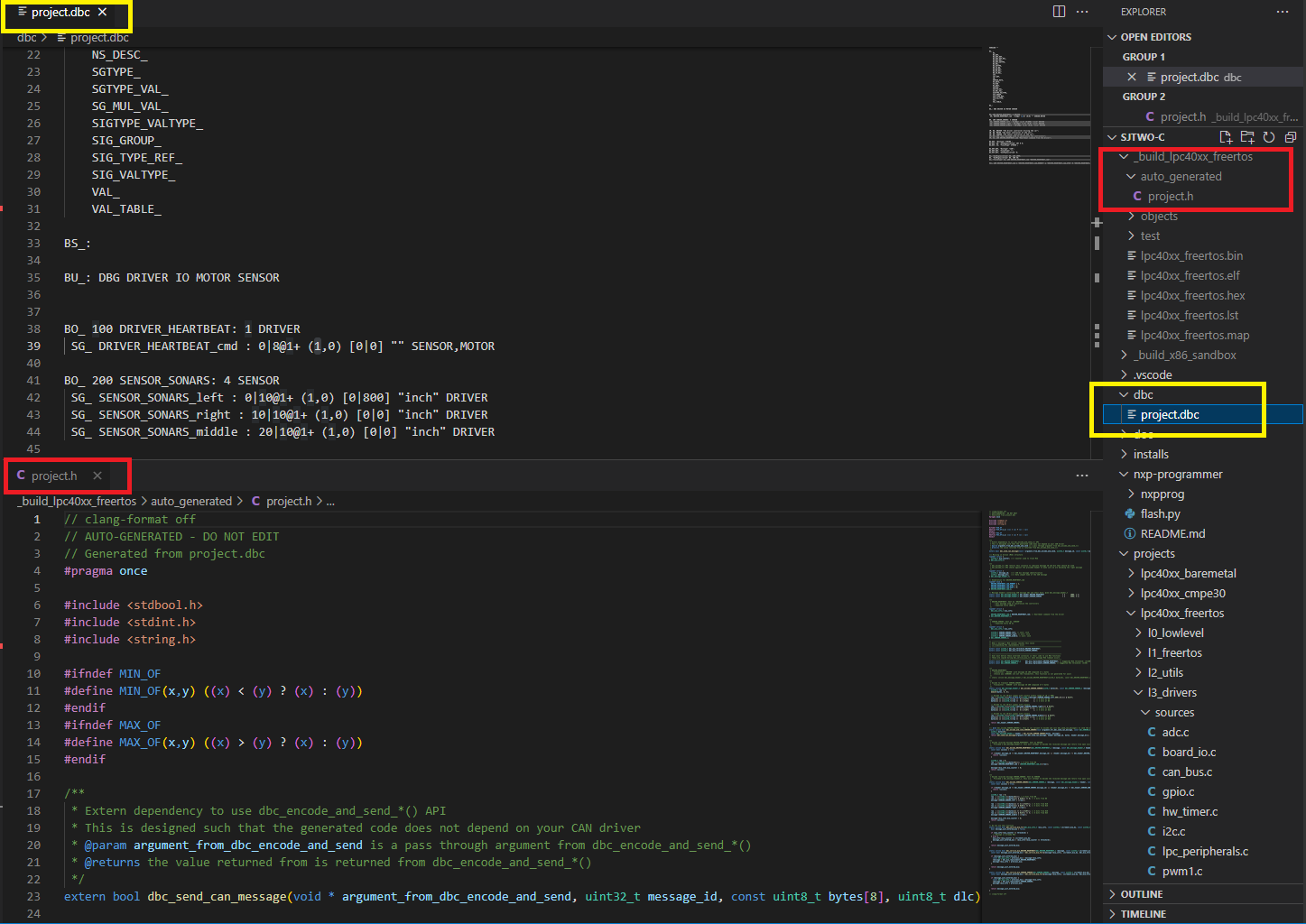
In this part, we will give meaning to various different bits and bytes that will be sent over the CAN bus. We are giving you a reference of MOTOR_CMD message, and in the sample dbc file located in your project folder, there is also project.dbc. These are reference points only, and you should be creating your own DBC message and not use these references word by word.
The snippet below dictates the following and you can read about DBC files in detail here. Documentation about the code generation can be referenced here.
- A message with ID
100(decimal) will be sent and the name isMOTOR_CMD - This message will only be composed of a
1data byte - It is sent by a CAN bus node called the
DRIVER - First data field is
MOTOR_CMD_steerand it is a 4-bit field starting with bit 0- Intention is to send data in the range of -5 to +5
- Second data field is
MOTOR_CMD_drive- We designed this field to represent numbers between 0-9 as in 0 for stop, and 9 for highest speed
- The two data fields are received by a CAN bus node called the
MOTOR- There can be multiple receives separated by a comma, such as
MOTOR,IO
- There can be multiple receives separated by a comma, such as
BO_ 101 MOTOR_CMD: 1 DRIVER
 SG_ MOTOR_CMD_steer : 0|4@1+ (1,-5) [-5|5] "" MOTOR
 SG_ MOTOR_CMD_drive : 4|4@1+ (1,0) [0|9] "" MOTOR
Use the references and create your own message composed of "signals" that you wish to send from one microcontroller to another. We recommend that you create signals such as acceleration sensor value, or a button press value that you will send from one board to another.
Create your DBC
- Reference Part 4 and think about messages you will send between microcontrollers interfaced over the CAN bus. This could be acceleration sensor readings, or light sensor values.
- After you decide what data to transfer between controllers, think about the node names and add them to the BU line:
BU_: DBG DRIVER IO MOTOR SENSORat your DBC file
Part 1: Code Generation
In this part, we will auto-generate C code based on the DBC file. The significance is that we want to minimize code development that is responsible to send correct data set on the CAN bus. This not only removes the tedious work and allows the developers to focus on the CAN application, but also minimizes common bugs related to transmission of data on the CAN bus.
An important aspect of code generation is that you should not have an API that is not relevant for your CAN node. So if you are the DRIVER CAN node, then you should not have functions that are related to sending sensor values of the SENSOR CAN node. To accomplish this, from now on, you should be using the following to compile your code
-
scons --dbc-node-name=<node name>- Example:
scons --dbc-node-name=MOTOR - The node name should be one of the ones defined in your DBC file:
BU_: DBG DRIVER IO MOTOR SENSOR
- Example:
- This ensures that you will not generate any code that is not relevant for your CAN node
- The default behavior is that code is generated for "ALL" nodes, which is not something you should do and it should be used for purely test purposes only. Another positive side effect is that when the DBC gets bigger, you want to read the code that is only relevant for yourself.
Study Generated Code
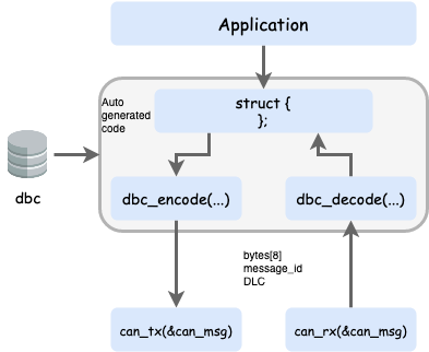
Please read the README.md file located in your project directory (or click here) to better understand the code generation aspect. Stop here, and spend 1-2 hours to understand the generated code that was created from your dbc file. We really mean it... spend time understanding the code because on the exams you will be asked to write this "encode" and "decode" code by yourself.
Unit Testing
For the code modules that use auto-generated code, you should not mock the generated code header file. This is because this is trivial code that does not involve any other code dependencies, and it is better to unit-test your code modules that use the auto-generated code without mocking. That means that in your unit-test file, simply #include the generated code, and let it encode and decode messages like it normally would.
Part 2: MIA Integration
In this part, we will provide instances of two key data types:
- MIA counter threshold to replace data structure instance
- MIA data structure instance itself
Well of course, we have to understand what is "MIA". MIA is Missing-In-Action, and the idea is that when an expected periodic message has not arrived, we replace it with safe values. For instance, when a temperature reading has not arrived, we can set the ambient temperature as a replacement value. This way, we do not have to repeatedly check if we can trust data values. In other words, if your RC car is controlling motors, we want to avoid this type of code:
void drive_motors(void) {
  if (!sensor_values_are_valid()) {
    motor_speed_percent = 0;
  } else {
    if (sensor > 40) {
      motor_speed_percent = 10;
    } else {
      motor_speed_percent = 0;
    }
  }
}
The code snippet above demonstrates that our code will be cluttered if we have to check for its validity everywhere. Instead, when periodic data goes missing, we just replace with zero, and therefore we can just retain this logic without checking for data validity upon each access of CAN network data.
void drive_motors(void) {
  if (sensor > 40) {
    motor_speed_percent = 10;
  } else {
    motor_speed_percent = 0;
  }
}
Take a note of the following auto-generated code which is asking for extern definitions from you:
// -----------------------------------------------------------------------------
// When a message's MIA counter reaches this value
// corresponding MIA replacements occur
// -----------------------------------------------------------------------------
extern const uint32_t dbc_mia_threshold_MOTOR_STATUS;

// -----------------------------------------------------------------------------
// User must define these externed instances in their code to use MIA functions
// These are copied during dbc_decode_*() when message MIA timeout occurs
// -----------------------------------------------------------------------------
extern const dbc_MOTOR_STATUS_s         dbc_mia_replacement_MOTOR_STATUS;
You will have to define the extern data values in a code module such as can_mia_configurations.c You can choose your own MIA replacement values, but if you leave it un-initialized they may be assumed as zero due to ANSI C standards.
// @file can_mia_configurations.c

const uint32_t dbc_mia_threshold_MOTOR_STATUS = 500; // 500ms

// Leave uninitialized if we wish to accept zero values as sane MIA replacement
const dbc_MOTOR_STATUS_s dbc_mia_replacement_MOTOR_STATUS;
Handle your MIA
After defining the data above in a file such as can_mia_configurations.c, invoke the MIA management in one of your periodic functions like so:
// @file periodic_callbacks.c
void periodic_callbacks_10hz(void) {
  can_handler__manage_mia_10hz();
}

// @file can_handler.c
void can_handler__manage_mia_10hz(void) {
  // We are in 10hz slot, so increment MIA counter by 100ms
  const uint32_t mia_increment_value = 100;

  if (dbc_service_mia_MOTOR_STATUS(&can_msg__motor_status, mia_increment_value))) {
    // Take action when a message has gone MIA?
    // Maybe light up an LED?
  }
}
Part 3: Encode and Decode
Encoding is used when you wish to transmit a data structure to the CAN bus. Obviously, this should only be used for a message that you are a transmitter of. Remember that no two nodes shall transmit the same message on a CAN bus. For more details about the auto-generated DBC API, see the following examples: Exploring DBC Autogenerated API.
// @file can_handler.c

// We are assuming that we have a 10hz function in which we wish
// to transmit all messages that should be sent at 10x per second
void can_handler__transmit_messages_10hz(void) {
  // Realistically, this message should be populated by a dedicated code module
  // TODO: Populate dbc_SENSOR_SONARS_s struct members
  dbc_SENSOR_SONARS_s sensor_struct = {};

  // Encode struct to bytes of the CAN message
  can__msg_t can_msg = {};
  const dbc_message_header_t header = dbc_encode_SENSOR_SONARS(can_msg.data.bytes, &sensor_struct);

  can_msg.msg_id = header.message_id;
  can_msg.frame_fields.data_len = header.message_dlc;
  can__tx(can1, &can_msg, 0);
}
On the receiving side, you should empty out all CAN frames received from the CAN driver, and then handle it in sort of a brute force approach.
// @file can_handler.c

void can_handler__handle_all_incoming_messages(void) {
  can_msg_t can_msg = {};
  dbc_MOTOR_CMD_s decoded_motor_cmd = {};

  while (can__rx(can__1, &can_msg, 0)) {
    // Construct "message header" that we need for the decode_*() API
    const dbc_message_header_t header = {
      .message_id = can_msg.msg_id,
      .message_dlc = can_msg.frame_fields.data_len,
    }

    // Even if incoming message is NOT motor cmd, our decode functions
    // will gracefully handle it because we provide valid "message header"
    dbc_decode_MOTOR_CMD(&decoded_motor_cmd, header, can_msg.data.bytes);
  }
}
And, don't forget MIA management of the message as mentioned in the section above.
Part 4: CAN Application
In this part, we will focus on the CAN based application. In particular, a controller will send sensor data information on the CAN bus, and another controller will receive the data, interpret it, and print it out.
Summary of your overall tasks:
- Define a DBC message for some data you wish to send
- Use Board #1 to encode and transmit the data periodically
- Use Board #2 to decode the received frame and do something with the received data
- And of course, be creative
Part 5: BusMaster
In this part, you will connect your CAN bus over a PCAN dongle, and view your data on "Bus Master" which is an open source program to view CAN bus messages. You will connect the PCAN dongle over to a DB9 connector that is connected to your CAN bus.
Follow this link and setup your Bus Master, and follow the steps to install, configure, and explore the program.
Final Requirements
- New message added in DBC
- Encode and Decode use the generated code based on the DBC
- Demonstration of the MIA (light up LED when message is missing)
- Unit-tests of the new code modules
- Demonstration of your CAN messages also appearing in the BusMaster
Unit Test Hints
TODO
LAB: RC Car Infrastructure
We are now on a roll . . . we are now going to work with multiple controllers that are interfaced to the CAN bus and react to each other's data. Please be sure to read this article.
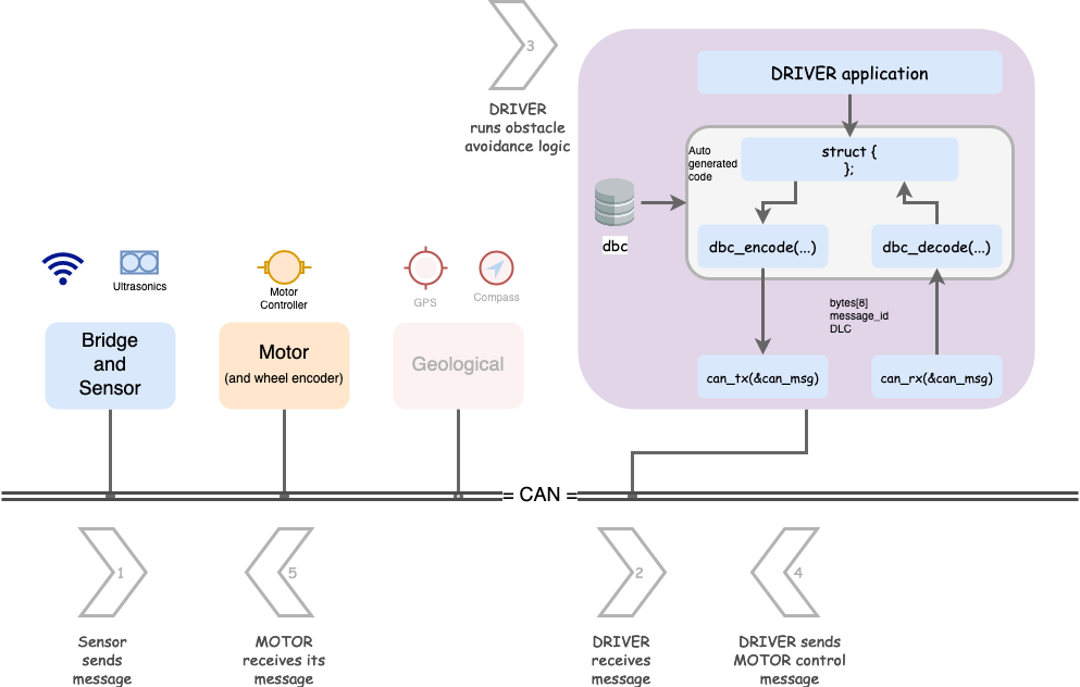
In this lab, we are going to setup basic building blocks of your autonomous RC car. Here is a required article you should read first. The outcome of the assignment is potentially multiple Gitlab Merge Requests MR - one for each controller. You will not only be setting up controllers that are communicating and reacting to data, but will also use BusMaster to demonstrate your data graphs of the CAN messages.
- Driver node
- Handles received CAN messages from the Sensor node
- Sends commands to the Motor Controller node
- Sensor node sends out sensor messages
- Optional to add real sensors, otherwise we suggest an incremeting distance sensor value sent on the CAN bus
- Feel free to add debug counters, something as simple as the 1Hz callback count
- Optional to add real sensors, otherwise we suggest an incremeting distance sensor value sent on the CAN bus
- Motor Controller node that receives commands
- Optional to add real servo (or motor) controller
- Feel free to add debug counters, something as simple as the 1Hz callback count
This will be a RC car GROUP assignment, meaning multiple MRs for your larger RC car team.
- Driver node will have most of the code, which will intercept Sensor node messages and send Motor controller commands
- Sensor node will at minimum send some kind of sensor values (could be fake ones)
- The Motor Controller code is simple and doesn't need to do much other than receive its motor commands CAN message from the Driver node.
Part 0: DBC
In this part, you should define the following CAN messages in the DBC file:
- Sensor node messages
- Transmit: At minimum, front, left, and right sensor reading (usually ultrasonic distance sensor)
- Motor Controller node messages
- Receive: Steer and wheel control messages (transmitter will be Driver node)
- Driver node messages
- Transmit: Steer and wheel control messages
- Potentially debug information because you will receive Sensor node message(s) and transmit to Motor Controller node
Remember YAGNI, do not over-engineer things. Invent minimal DBC and code because there will be less code to write, less code to test. Do not solve for theoretical problems until you really see them. We would encourage you to have your steering values between -2 to +2 and wheel speed as kph with fraction of 0.1
Part 1: Driver Obstacle Avoidance Code Module
Design your code modules with simple input, and output as your first preference. Simple I/O modules are easier to code and test for. For example, the driver code module should be like the following:
// @file driver_logic.h

// Assuming this data structure as input from the DBC
struct dbc_SENSOR_data_s;

// Assuming this data structure as output from the DBC
struct dbc_MOTOR_command_s;

// This should copy the sensor data to its internal "static" struct instance of dbc_SENSOR_data_s
void driver__process_input(dbc_SENSOR_data_s sensor_data);

// This should operate on the "static" struct instance of dbc_SENSOR_data_s to run the obstacle avoidance logic
dbc_MOTOR_command_s driver__get_motor_commands(void);

/**
 * Wow...
 * Is our Driver really going to be that simple? --> Yes, you should at least try to keep it that way.
 *
 * It takes a lot of effort to solve problems with minimal code
 * It is easy to write more code, and appear to be busy solving nasty intertwined bugs
 *
 * Yes, it is true that when you add GPS heading, your driver logic will change,
 * but we can work on that after this stage
 */
Part 2 gives suggestion regarding which code module should be invoking the driver__process_input() function.
Part 2: Handle CAN
Code modules like driver_logic.h should not be dealing with the CAN driver. All this code module should say is that "give me sensor values and I will give you back motor commands". This is part of modularizing code, and the path to not create The Blob.
Let us create a dedicated code module to handle arriving CAN messages
// @file msg_bank.h
#include "can_bus.h"

// Invoke this method in your periodic callbacks
void msg_bank__handle_msg(const can_msg_t *message);

// MIA management:
void msg_bank__service_mia_10hz(void);

// "GET" APIs to obtain latest data
dbc_SENSOR_data_s msg_bank__get_sensor_data(void);
dbc_some_data_s msg_bank__get_other_data(void);
// @file msb_bank.c
// Include code modules that should receive their decoded CAN messages
#include "driver_logic.h"
#include "another_code_module.h"
static dbc_SENSOR_data_s sensor_data = {};
static dbc_some_data_s some_data = {};
void can_bus_handler__process_all_received_messages(void) {
can_msg_t can_msg = {};
// Receive all messages
while (can_rx(can1, &can_msg)) {
const dbc_message_header_t header = {
.message_id = can_msg.msg_id,
.message_dlc = can_msg.frame_fields.data_len,
}
if (dbc_decode_sensor_data(&sensor_data, header, can_msg.data.bytes)) {
}
if (dbc_decode_some_data(&some_data, header, can_msg.data.bytes)) {
}
}
}The testing of the can_bus_handler.c should be easy because all it does is decodes messages, and routes the data to the code module owners. You can either have can_rx_StubWithCallback() or use can_rx_ReturnThruPtr() variants to carry out your unit-tests.
Part 3: Handle CAN transmit
The driver_logic.h processed incoming data, and ran its algorithm to compute the motor and wheel commands. we also need to send the CAN messages out.
The following approach is suggested and please reference this article on the encode_and_send() API variant.
// @file can_bus_handler.h
#include "can_bus.h"

// Maybe at 10Hz, send the motor commands
void periodic_callbacks_10Hz(void) {
  // TODO Fix this
  const dbc_MOTOR_command_s command = driver__get_motor_commands();

  // Encode and send the CAN message
  dbc_encode_and_send(&command);
}
If you define dbc_send_can_message() then it can provide convenience of sending the CAN messages:
void can_bus_handler__transmit_messages(void) {
  // TODO Get struct to send from driver_logic.h

  // This function will put everything together and invoke dbc_send_can_message() internally
  // This avoids us having to re-construct CAN message data structure repetitively
  dbc_encode_and_send_DBC_TEST2(NULL, &dbc_MOTOR_commands);
}

// define this at maybe dbc_to_can_driver_glue.c
bool dbc_send_can_message(void * argument, uint32_t message_id, const uint8_t bytes[8], uint8_t dlc) {
  can_msg_t msg = {};

  msg.frame_fields.dlc = dlc;
  msg.message_id = message_id;
  memcpy(msg.data.bytes, bytes, 8);

  return can_tx(can1, &msg, 0);
}
Part 4: BusMaster Debugging
In this part, you will use BusMaster to demonstrate:
- Graphical view of the sensor message
- A common graph where you can plot motor command with respect to sensor messages
Conclusion
For the Merge Requests, we expect that you:
- Demonstrate code modules, with unit tests
- Build the DRIVER node logic that receives messages, and transmits motor controller message
- Build the SENSOR node that sends sensor data
For the BusMaster portion, we expect that you:
- Open DBC file in BusMaster
- Design a simple GUI or graphs in BusMaster that demonstrates that as the SENSOR node distance data slowly increments, the motor controller commands make reasonable decision
- Impress the ISA team
LAB: Geo Controller
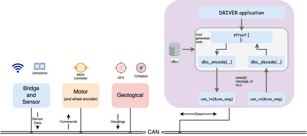
In this lab, we will add the Geological Controller to your RC car. Please review this article to figure out the roles and responsibilities of different controllers in your RC car.
The high-level idea is that:
- Geo Controller receives a destination in the form of latitude and longitude
- Geo Controller also has a link to the GPS module
- You can more or less use the Pythagorean theorem to compute the heading degree for the Driver Controller
This will take some research but the earth is not flat (it is really not flat), and so if you use the Pythagorean theorem, your heading degree may not be fully accurate, but it will work on the scale of your RC car unless you are sending it long distance such as US to Canada.
Another research item is that you will have to eventually align your GPS degree to the Compass degree. For example, your compass degree may have 90 degrees as North, whereas your GPS may or may not agree, but for this lab, we can assume fake values of the compass and focus only on the GPS portion. When you eventually fix this logic, no other controller would need to know because they are abstracted away as they only focus on the destination and current heading, and how you compute these numbers is not a concern for other controllers as long as you do it right.
Part 0: DBC
In this part, you should define the following CAN messages in the DBC file:
- GPS destination message
- The Bridge Controller should send the destination to Geo Controller
- This should include longitude(float) and latitude (float).
- Assign the number of bytes and change the range as per your requirement.
DBC Example 1 for GPS destination message:
BO_ ID GPS_DESTINATION_LOCATION: 8 TX_NAME
 SG_ GPS_DEST_LATITUDE : 0|28@1+ (0.000001,-90.000000) [-90|90] "Degrees" RX_NAMES
 SG_ GPS_DEST_LONGITUDE : 28|28@1+ (0.000001,-180.000000) [-180|180] "Degrees" RX_NAMES
DBC Example 2 for GPS destination message:
In this example, it would help you get around the fact that a "float" is only a 32-bit imprecise number. More particularly, it cannot host a decimal precision past 6 decimals. Furthermore, if the significant number increases (such as 0.123 to 123.123), then the decimal precision may be reduced below 6 decimals.
In order to effectively send high precision numbers, you can scale them manually. So if you wanted to send 123.012345, then you can manually send the number as 123012345.
BO_ ID GPS_DESTINATION_LOCATION: 8 MOBILE_APP
 SG_ GPS_DEST_LATITUDE_SCALED_100000 : 0|32@1- (1,0) [0|0] "Degrees" RX_NAMES
 SG_ GPS_DEST_LONGITUDE_SCALED_100000 : 32|32@1- (1,0) [0|0] "Degrees" RX_NAMES
2. Compass heading and distance message
- The Geo Controller should send this message to the LCD or Bridge Controller
- Include 0-360 degrees of current heading(after using haversine formula) and the bearing angle(optional) (from the Compass)
- Include the distance to the destination in meters in order to update the real-time remaining distance on the mobile application.
- Assign the number of bytes and change the range as per your requirement.
DBC Example for the compass heading and distance message:
BO_ 100 GEO_STATUS: 8 TX_NAME
  SG_ GEO_STATUS_COMPASS_HEADING : 0|12@1+ (1,0) [0|359] "Degrees" RX_NAMES
  SG_ GEO_STATUS_COMPASS_BEARING : 12|12@1+ (1,0) [0|359] "Degrees" RX_NAMES
  SG_ GEO_STATUS_DISTANCE_TO_DESTINATION : 24|16@1+ (0.1,0) [0|0] "Meters" RX_NAMES
Part 1: Driver Obstacle Avoidance Code Module
Remember our last code module for the driver? We will extend it to also absorb the Geo Controller message, and then we will use this information to figure out the motor controller commands.
// @file driver_logic.h

// Assuming these data structures from the generated DBC
struct dbc_SENSOR_data_s;
struct dbc_MOTOR_command_s;
struct dbc_GEO_status_s;

// This should copy the sensor data to its internal "static" struct instance of dbc_SENSOR_data_s
void driver__process_input(dbc_SENSOR_data_s sensor_data);
void driver__process_geo_controller_directions(dbc_GEO_status_s geo_status);

// This should operate on the "static" struct instance of dbc_SENSOR_data_s to run the obstacle avoidance logic
dbc_MOTOR_command_s driver__get_motor_commands(void);
Part 2: The power of TDD
The beauty of unit-tests is that when we add additional logic, we can still ensure that our previously written code is not going to break or malfunction. The Geo Controller message should have no impact on the output of the motor controller commands if there is an obstacle avoidance actively being used. Only if all sensors show that there is no obstacle should your RC car obey the Geo Controller commands, and steer the car in the right direction.
Please ensure that your existing unit tests pass, and then add the additional logic necessary to handle the steering angle based on the Geological controller's status message (compass headings).
Part 3: Extras
You should invest in easy diagnostic functionality, so slap on a couple of bright LED indicators (driven by a higher current transistor or MOSFET) to indicate things such as:
- An obstacle is in the near vicinity and GPS heading is not being followed
- This will tell you if the RC car is following the GPS or avoiding an obstacle
- A ring LED device that indicates where the RC car is trying to go
- Sparkfun device link may be non-trivial to drive this LED device but should be worth the effort
While this part is technically "extra credit", implementing these kinds of easy features will save you a ton of time later in the project.