SJSU - CmpE243 -Industrial Applications with CAN Bus
CmpE243
- CmpE243 - What is it about?
- Advise for the Class
- Introductory Labs
- LABS
- Lab: Queue
- LAB: Unit testing with mocks
- LAB: GPS and UART
- LAB: CAN bus
- LAB: CAN bus with DBC
- LAB: RC Car Infrastructure
- LAB: Geo Controller
- Class Project and Useful Articles
- Project Introduction and Guidelines
- Project Hints
- Unit Testing code that touches the HW registers
- Use single periodic callback if possible
- CANTools
- Exploring DBC Autogenerated API
- Unit-Test Basics and Mocks
- Navigating a Processor's Reference Manual
CmpE243 - What is it about?
These are the learning objectives of the class:
- Realtime data processing and communication between different controllers over the CAN Bus
- Collaborative learning
- Communication (Slack vs. Email vs. video conference)
- Software Development
- Code modules
- Unit-tests
- Code generation
- Engineering Tools
- Git
- Linux, command-etc
- CAN Bus
- CAN tools (ie: BusMaster)
- comma.ai demonstration
- DBC file
Advise for the Class
RC car parts
- Read this article
- Begin to acquire parts for the RC car (including sensors etc.)
- Reminder:
- Your worth as new graduate should be about $50/hour (as an engineer as of 2022)
- Therefore, buy $30 sensor rather than $2 ebay sensor to avoid writing software to deal with unreliable sensors
General Advice
-
I would Highly recommend that future peers take this class.
-
Reduce amount of concurrent classes / work hours while taking this class.
-
Take this course if you really want to learn, not just to complete credits. If you are not contributing in group project/ group lab assignments, you might get the grades but not what this class is for.
-
Focus on the class heavily during the first month especially given the tedious first couple of labs and the CAN bus lectures.
- Take CMPE244 first in order to fast pace your learning for this class.
- Start right from the moment you register your course. knowing required tools, skills and software would help a lot
- For your personal development: Take the lab assignments and unit tests seriously. This is not for the grade, but for personal learning, because this material is directly applicable to interview questions for Embedded/Firmware engineering positions. I had multiple interviews where I directly used concepts/problem solving skills I developed while completing the lab / project assignments. For the team project: Take the time to discuss among the team members and vote/decide on a weekly "team meeting" time-slot. This will serve as your weekly "planning meeting" where everyone comes together quickly to discuss past progress, plan the next individual assignments, and coordinate the next in-person integration/testing session. Take the time to coordinate weekly in-person integration/testing sessions. This turned out to be most convenient to do on-campus, on weekends. The student union is open on the weekends, and has working space/power outlets. This is a great time to take everyone's individual implementations, and integrate them with the physical hardware, as well as debug all the problems that will inevitably come up.
- Spend a good amount of time from day one of class in knowing every aspect of assignment.
- Earnestly engage with the material. Don't take shortcuts or do the bare minimum for labs and project. Get comfortable with the sjtwo workspace and build tools and use them frequently (several times a week). Be honest about your shortcoming and what you don't understand so you can do something about it, there's an economy to honesty. You're here to learn and grow as an engineer.
- Don't be afraid to ask questions or for more examples.
- Don't leave the labs until the last minute. It's better to make small meaningful progress as you are technically doing your project while doing the labs. Rushing the labs will lead to a lesser project down the road.
- This is a 3 man project done by 5-6 people. It will seem as if there is not enough stuff for people to do, but there is always something to find to do.
- Understand CAN bus and how to read sensor datasheets
- Make teams early and get the hardware part- RC car (it takes time in assembly), sensors and other stuff. Focus on the lectures and labs they will be used in the RC Car software development. And be excited about learning new everyday.
- Should have good experience in coding and also should have worked on atleast one development board to get the maximum benefit of the class.
- A strong suggestion to take this course with special interest and prepare in advance a little to get the most out of it
Advise from 2024 class:
- Don’t miss class. Not able to catch up
- Be consistent, hardwork and you will see the results at any point of the class.
- Read the lab assignments and requirements multiple times to get the better understanding of the lab. This class is rigorous; planning and starting early on labs and projects will be the best help.
- Definitely take the class to learn about CAN and embedded
- This is definitely a fast paced course, it is recommended not to take this class when you plan to take 4 subjects.
- Plan ahead. This is possibly the best advice. Analyse what others have done in the past and make actionable plans well in advance. Go through all the team reports from past 2 semesters at least.
- Start your homework early.
- 1. A piece of advice I received from former students is to wholeheartedly enroll in this class if you aim to pursue a career in the embedded industry, and I support that. 2. I personally know individuals who transitioned from non-embedded backgrounds to thriving in reputable companies after taking Preet’s class. 3. Encountering such committed professors, relevant courses, detailed projects, and thorough documentation is rare. Therefore, I urge you to seize this opportunity. The knowledge gained here is practical and invaluable, so push yourself to explore additional credit sections in assignments, experiment with code, and go the extra mile—you won't regret it! As Preet often emphasizes, there is no magic.. Hard Work will be paid off well.
- Invest enough time initially to get to know the development environment and sjtwo board. Dont rush unit tests, take time to understand.
- 1. Start looking for parts and begin ordering them as soon as you establish your team. 2. Don't be afraid and wait for the last minute to ask questions in Slack. People need time to view your message and respond. Also, you are likely experiencing a similar problem as someone else. 3. Consider your hardware design early in the course so that you can order misc components such as extra wires, perfboard, resistors, stand offs, etc.
- it is not easy
- Think about the end-goal from Day1. It is not about this/next week's assignment submission. Even if you struggle initially to complete assignments, do it the right way.
- Try to work earlier, contact with teammates earlier.
- Definitely starting early. As a student who experienced undergrad in a quarter system school to now being in a semester school, the first half of the class ran extremely similarly to that of the quarter system: fast-paced, but the work is manageable as long as you start early. The amount of work you have in other classes is irrelevant as long as you manage your time well and appropriately. Starting early doesn’t necessarily mean finishing early, even if it is a plus!
- Put in the time to understand how things work and start on the assignments/projects right away. Ask questions.
- Wander through the code there's a lot to learn!! Just be curious and the rest will come super easily :)
Introductory Labs
LAB: Periodic Scheduler
The objective of this assignment is:
- Set up your development environment
- Learn how to run unit-tests
- Trial how to input your code to the Periodic Scheduler
For CmpE243, we will not be focusing on typical RTOS tasks like CmpE244. The reason is that we wish to use an approach that is typically seen in the Automotive industry, which is to design the logic of your autonomous RC car based on software instructions that occur periodically and consistently.
Part 0: Build Environment
Set up your development environment for this portion of the lab. Follow through and read all of the README files carefully that are linked here. Make sure you are able to run the unit tests, and also compile a hex file that you can load onto your board.
You can watch the following video to get started:
Part 1: Blink LEDs
For this portion, edit the code such that it will start to blink four LEDs driven by the periodic scheduler. In particular, read the documentation of the main.c file, and enable the code for the periodic scheduler.
Study the overall structure of main.c, and then switch a #if (1) to #if (0) such that it will disable two blinky tasks, and instead run the periodic scheduler. The name "periodic scheduler" may sound fancier than what it actually is, but this is just a trivial piece of code that invokes function at periodic_callbacks.c file.
// main.c

static void create_blinky_tasks(void) {
  /**
   * Use '#if (1)' if you wish to observe how two tasks can blink LEDs
   * Use '#if (0)' if you wish to use the 'periodic_scheduler.h' that will spawn 4 periodic tasks, one for each LED
   */
#if (0)
  // ...
#else
  periodic_scheduler__initialize();
  UNUSED(blink_task);
#endif
}

// periodic_scheduler.c

void periodic_scheduler__initialize(void) {
  /**
  ...
  */
  static StackType_t hz1_stack[4096 / sizeof(StackType_t)];
  static StackType_t hz10_stack[4096 / sizeof(StackType_t)];
  static StackType_t hz100_stack[4096 / sizeof(StackType_t)];

  /**
  ...
  */
}
There are a few things to note for future reference:
- The stack size is chosen with a same value, and depending on the complexity of the functions you invoke at the
periodic_callbacks.cfile, you may have to increase this memory size. Also note that there are five tasks total that run the periodic callbacks, so if you input 2K, then you will end up using 10K for the memory footprint. Recommended size is 2-4K. - The logic at
periodic_callbacks.cthe file should be function calls into your other code modules. This way, unit tests of this file will remain simple. You do not want to input branch statements here because this would make your code less modular, and difficult to unit-test.
Part 2: Switch and LED code module
Insert additional code to one of the periodic callbacks, and then observe its operation. In the example below, we are going to demonstrate the right way to build a module that reads a switch and lights up an LED.
DO NOT do the following because what you have done is that cluttered all the things that need to occur periodically. If we go down this path, you will end up creating a giant periodic_callbacks.c file that will be difficult to test, and your code will not be modular or broken down into these pieces. Unit-testing code will also be difficult because now you have to not only test the switch and LED logic but also test more unrelated subsequent code.
// periodic_callbacks.c -- BAD example

static gpio_s my_led;
static gpio_s my_switch;

void periodic_callbacks__initialize(void) {
  my_led = gpio__construct_as_output(GPIO__PORT_2, 0);
  my_switch = gpio__construct_as_input(GPIO__PORT_2, 1);
}

void periodic_callbacks__1Hz(uint32_t callback_count) {
  gpio__toggle(board_io__get_led0());

  if (gpio__get(my_switch)) {
    gpio__set(my_led);
  } else {
    gpio__reset(my_led);
  }
}
Instead, follow good code design, and create "modules" for your code. Using this approach, you have refactored your switch and LED logic to a new code module: switch_led_logic.h. You can test this code module separately and then testing the periodic_callbacks.c a code module is also straightforward since you only have to set up a couple of "expect" function calls.
// periodic_callbacks.c -- Good example

#include "switch_led_logic.h"

void periodic_callbacks__initialize(void) {
  switch_led_logic__initialize();
}

void periodic_callbacks__1Hz(uint32_t callback_count) {
  gpio__toggle(board_io__get_led0());

  switch_led_logic__run_once();
}
Of course, you are not done yet, and you also have to modify test_periodic_callbacks.c
#include "Mockboard_io.h"
#include "Mockgpio.h"

// Add mock of your new code module
#include "Mockswitch_led_logic.h"
#include "periodic_callbacks.h"

// Add expect during the periodic_callbacks__initialize() function
void test__periodic_callbacks__initialize(void) {
  switch_led_logic__initialize_Expect();
  periodic_callbacks__initialize();
}

void test__periodic_callbacks__1Hz(void) {
  gpio_s gpio = {};
  board_io__get_led0_ExpectAndReturn(gpio);
  gpio__toggle_Expect(gpio);

  switch_led_logic__run_once_Expect();
  periodic_callbacks__1Hz(0);
}
Part 3: Experiment with Task Overrun
Deliberately overrun one of the periodic tasks and observe that your board will reboot. Since this will be sort of a "throw-away" code, you can opt to skip the unit-tests. Here is a sample code that will deliberately reboot the processor because of the missed deadline of the 1Hz function.
// periodic_callbacks.c

// Include these files for RTOS task delay function
#include "FreeRTOS.h"
#include "task.h"

void periodic_callbacks__1Hz(uint32_t callback_count) {
  gpio__toggle(board_io__get_led0());

  // On the fifth function call to this function, sleep for 1000ms
  if (callback_count >= 5) {
    vTaskDelay(1000);
  }
}
It is strongly advised NOT to skip the unit-tests in general. But if you are purely doing a code prototype to try things out, then use the scons --no-unit-test command.
What did you learn?
- Work with the periodic callbacks to add your code
- Design small code modules, and set up their expectation in unit-test code
- The first-hand account of what happens when you miss the deadline of a periodic callback
LAB: Git
This is definitely not an exhaustive tutorial about learning Git... Google would be better to reveal several great tutorials about Git. What we focus on instead is a simplistic workflow about publishing a "Pull Request" in Git.
What is Gitlab?
Gitlab provides services that allow hosting your project on a remote repository and provides additional features that help in continuous integration and deployment. Such as code sharing, code review, and bug tracking.
Part 0: Setup Gitlab account
For better or worse, we have decided to use Gitlab.com for the repository. You are also required to use this Gitlab repository because that keeps the entire class aligned to a single server type and reduces fragmentation while increasing the efficiency of the teacher and the ISA team.
For this part, establish your Gitlab.com account.
How to set up a Gitlab account?
- Go to GitLab.com and create an account.
- Sign in to GitLab.
In addition, also install Git to your machine such that you can successfully execute the git Commands from a terminal.
- Download git from GIT_Install and install git.
- Check git is installed on your system by using the "git --version" command in the terminal.
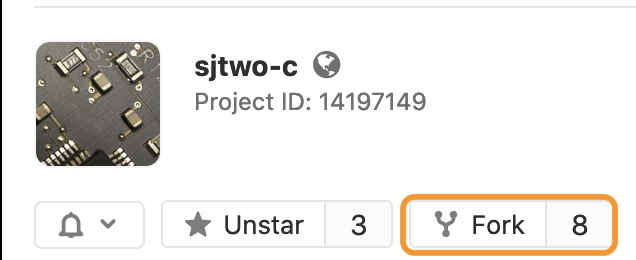
Part 1: Fork SJ2-C Project
When you fork a project, you essentially create a copy of the original SJ2-C repository. This will be your version of the forked project, and you can use this throughout the semester for your private workspace to do the lab assignments.
Browse to the SJtwo-c repository, and click on the Fork button.
After you fork the repository, make sure you set the permissions to "public". Do this by going into your newly forked repository settings, and look for the "Visibility" setting.
How to change project visibility
- Go to your newly forked project’s Settings
- Change Visibility Level to Public
Part 2: Basic Git Commands
INIT
The first thing you want to do before you init is to add a project on the Git website to see the “Setting up a new Git repository” section. If you have a folder with code that is not on Git, and you wish to put it on the Git server, then you need to initialize Git into your folder. This creates a .git folder, and the current directory is now a Git repository. The .git folder contains Git information such as branches. Initializing your folder is local to your computer and does not yet upload onto the server.
# To add your project to the git
# Initialize current directory
$ git init

# Initialize selected directory
$ git init <directory>
CLONE
If you see a repository that you want to work on, you can “clone” it into a directory and start working on it. Cloning it will download the entire repository as well as a .git folder. Note that the clone is different from “pull”. This will be explained later. Just use this command once at the beginning of the project unless you want multiple folders.
# Downloads entire repository to current directory
$ git clone <repo>

# Downloads entire repository to selected directory
$ git clone <repo> <directory>
The difference between forking and cloning a GIT project means when you fork a repository, you create a copy of the original repository (upstream repository) but the repository remains on your personal Gitlab account. Whereas, when you clone a repository, the repository is copied onto your local machine with the help of Git.
Part 3: Branch Workflow
The process of checking-in new code to your forked repository will involve "Branch Workflow". There are actually a number of ways to contribute code to your repository, and the branch workflow is just one of them that we will choose to use.
We are not going to discuss that in detail because it is already captured well in this awesome article. We will summarize the process that you will use to do this. The $ indicates the commands you should try.
# See what is going on
$ git status
On branch master

# Create a new "branch" of code to work on
# You can use any name, and feature/foo is just a convention
$ git checkout -b feature/gpio_blinky_in_periodics
Switched to a new branch 'feature/gpio_blinky_in_periodics'

# Add or modify a file we want
$ touch file.txt

# Tell git to add it to be committed
$ git add file.txt

# Check what is going on
$ git status
On branch feature/gpio_blinky_in_periodics
Changes to be committed:
(use "git reset HEAD <file>..." to unstage)

new file: file.txt

# Commit the change with a message
$ git commit -m "added file.txt"
[feature/gpio_blinky_in_periodics 5f76839] added file.txt
1 file changed, 0 insertions(+), 0 deletions(-)
create mode 100644 file.txt

# Check what is going on
$ git status
On branch feature/gpio_blinky_in_periodics
nothing to commit, working tree clean
Part 4: Merge Request (MR)
The typical name of a request to merge code is called a "Pull Request" or a "Merge Request". This is the chance to review the code and merge the code. In the end, Part 3 you have a branch that only exists on your computer. In case you lose your computer or your storage device dies, then you will lose any work even though you have "committed" a change.
The distinction is that a commit only commits to your storage device, but does not send the data or the branch to the Git server. To actually push the code to the Git server, simply type git push origin head.
$ git push origin head
Enumerating objects: 3, done.
Counting objects: 100% (3/3), done.
Delta compression using up to 12 threads
Compressing objects: 100% (2/2), done.
Writing objects: 100% (2/2), 262 bytes | 262.00 KiB/s, done.
Total 2 (delta 1), reused 0 (delta 0)
remote:
remote: To create a merge request for feature/gpio_blinky_in_periodics, visit:
remote:   https://gitlab.com/sjtwo-c-dev/sjtwo-c/-/merge_requests/new?merge_request%5Bsource_branch%5D=feature%2Fgpio_blinky_in_periodics
remote:
To gitlab.com:sjtwo-c-dev/sjtwo-c.git
 * [new branch]      head -> feature/gpio_blinky_in_periodics
This command will generate a URL for you, so copy and paste this URL to your web browser. For example, the URL above is: https://gitlab.com/sjtwo-c-dev/sjtwo-c/-/merge_requests/new?merge_request%5Bsource_branch%5D=feature%2Fgpio_blinky_in_periodics
This will lead you to generate your "Merge Request". At the end of the web page that loads, click on "Submit Merge Request". At this point, you can view the changes, get feedback from others, and if the code looks good, you can then merge the code. But wait ... rarely will you be able to merge code without iterating and revising it, and that is what Part 5 is for.
Part 5: Revise an MR
Granted that you have an MR already out there, and you have got feedback from others, this section will teach you how to revise or amend your code.
# Modify any code
# In this case, we will dump 'hello' to our previously committed file: file.txt
$ echo "hello" >> file.txt

# Check what is going on
$ git status
On branch feature/gpio_blinky_in_periodics
Changes not staged for commit:
  (use "git add <file>..." to update what will be committed)
  (use "git checkout -- <file>..." to discard changes in working directory)

	modified:   file.txt

# Add the file we want to re-commit (another commit on top of previous)
$ git add file.txt
$ git commit -m "Added hello to file.txt"

# Update the remote branch and the Merge Request
$ git push origin head
After the git push command, your MR will be updated on the browser. This way, you can continue to revise your MR per the suggestions of other people. When you are satisfied with your MR, you can seek approval and officially hit the Merge button on the Gitlab.com webpage.
Part 6: Final Step
After you have merged your MR, it is time to go back to the master branch and grab the latest changes. Other users may have merged their code also, so pulling the latest master branch is going to get you the latest and greatest code.
# Go to the master branch
$ git checkout master

# Pull the latest master
$ git pull origin master
Part 7: Going beyond . . .
There is of course A LOT more to Git, but once you master the basics, you can then Google your way through the rest of the world you will face such as:
- Handling merge conflicts
- Check out other people's branches
Rebase on the latest master branch.
$ git status
# Assume that you are on your feature branch

$ git checkout master
$ git pull origin master

# Go back to the previous branch you were working with (feature)
$ git checkout -

# Apply our commits to the latest master
$ git rebase master
Part 8: Steps to create MR for Lab Submissions
The process of checking-in new code to your forked repository will involve "Branch Workflow" as explained in PART 3. The following steps will help you to add new code/files for each of your lab submissions.
- Goto cmd OR terminal OR git bash. CD to the location of the cloned project(cd sjtwo-c/projects/lpc40xx_freertos/l5_application) and run the following commands.
 # You can use any name, it's better to use lab with the number as a branch name.
 # such as lab1,lab2
$ git checkout -b lab1
Switched to a new branch 'lab1'

# Add or modify files as per the given lab assignment
# for example lab 1 requires two files
$ touch lab_multitasks.c
$ touch lab_multitasks.h

# Check what is going on
$ git status
On branch lab1
Untracked files:
  (use "git add <file>..." to include in what will be committed)

	lab_multitask.c
	lab_multitask.h

# Tell git to add it to be committed
$ git add .

# Check what is going on
$ git status
On branch lab1
Changes to be committed:
  (use "git reset HEAD <file>..." to unstage)
	new file:   lab_multitask.c
	new file:   lab_multitask.h

# Commit the change with a message
$ git commit -m "added lab1 files"
[lab1 e88f23d] added lab1 files
 2 files changed, 0 insertions(+), 0 deletions(-)
 create mode 100644 projects/lpc40xx_freertos/l5_application/lab_multitask.c
 create mode 100644 projects/lpc40xx_freertos/l5_application/lab_multitask.h

# Check what is going on
$ git status
On branch lab1
nothing to commit, working tree clean

# Update the remote branch and the Merge Request
$ git push origin head
Enumerating objects: 3, done.
Counting objects: 100% (3/3), done.
Delta compression using up to 12 threads
Compressing objects: 100% (2/2), done.
Writing objects: 100% (2/2), 262 bytes | 262.00 KiB/s, done.
Total 2 (delta 1), reused 0 (delta 0)
remote:
remote: To create a merge request for lab1, visit:
remote:   https://gitlab.com/sjtwo-c-dev/sjtwo-c/-/merge_requests/new?merge_request%5Bsource_branch%5D=lab1
remote:
To gitlab.com:sjtwo-c-dev/sjtwo-c.git
 * [new branch]      head -> lab1


 # Assume that you are on your lab branch
 # To comeback to master branch
$ git checkout master- Create a merge request for each lab and use the merge request URL for your lab submissions.
- Please follow PART 4 to generate and submit "Merge Request" on Git.
- After submitting a merge request you will receive a new URL on the browser. Use that URL for your canvas submission.
- Follow the same steps for creating the next lab branch(such as lab2), add new files to the lab2 branch(such as lab_gpio.c and lab_gpio.h), and create a merge request for the submission after completing your GPIO driver.
for appropriate to; intended for More (Definitions, Synonyms, Translation)
Note make mention of More (Definitions, Synonyms, Translation)
Git Basics
What is Gitlab?
Gitlab provides services that allow hosting your project on a remote repository and provides additional features that help in continuous integration and deployment. Such as code sharing, code review, and bug tracking.
GIT Workflow
In Git there is the notion of a "Master" code base which contains the work of all contributing members in a project.
There are two basic workflows that you may follow when using Git for version control.
- Committing directly to the "Master" branch.
- Creating branches from the "Master" branch and merging them back in when ready.
This section of the guide will walk you through these two workflow strategies.
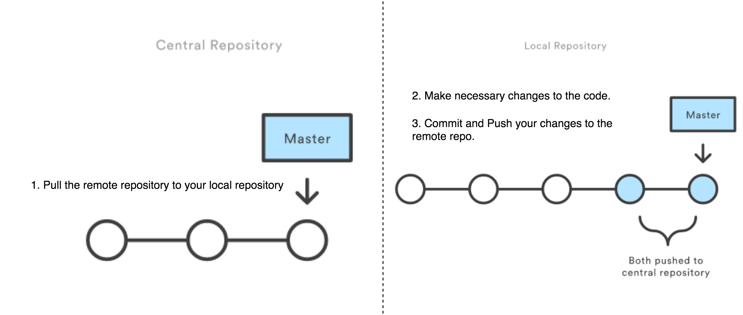
1. Working off the "Master" Branch
Working directly off the "Master" branch can be advantageous to smaller groups who rarely (if ever) work on the same portions of the code at a time.
.png)
The basic workflow for this method is as follows:
- "Pull" from the Master branch to ensure the local copy contains the latest version of the code.
- Make necessary changes to the code in your local repository.
- Commit your changes.
- "Push" your changes to the remote repository.
In git commands this would look like this:
# Make sure you are on master branch
git checkout master

# Make sure you have the latest code
git pull origin master

# Make your changes to your code
# Add files you may have changed to your commit
git add <file1> <file2> ...
# Add all untracked files to your commit
git add .

# Commit your changes
git commit -m "<commit message here>"

# Push your changes
git push origin HEAD
2. Working with feature branches
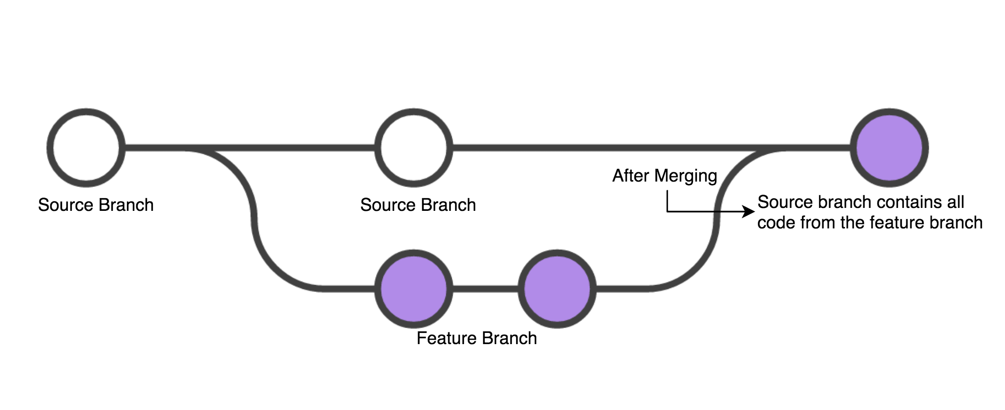
The second workflow takes advantage of the branching system in git. To protect your Master branch from code that may break your build or introduce bugs we can create what is called a "feature branch." These branches contain your development code and isolate it from the main code until you are ready to merge them together.
The workflow is as follows:
- Do a "git fetch" to obtain the latest version of your source branch.
- Check out a new branch.
- Perform your work on your new branch (be sure to make regular commits to avoid losing any of your work.)
- Merge the two branches.
# Checkout your "source" branch (the branch you want to base your code off of)
git checkout master

# Obtain the latest code
git fetch origin

# Create a new branch from your source branch
git checkout -b <new branch name>

# Make your code changes and commit them regularly
git add <file1> <file2> ...
git commit -m "<commit message>"

# Push your changes to your FEATURE branch
# GIT server knows this branch after the push and other people can also check-out your branch
# But this branch is not yet merged to the master branch
git push origin HEAD
When you are ready to merge your branch back into the source branch there are two routes you may take:
- Merge your feature branch directly into the source branch.
- Open a pull request for peer code review prior to merging your branch.
To merge your feature branch into the source uses the following workflow:
- Check out the source branch.
- Ensure your source branch contains the most updated code from the remote repo.
- Merge your feature branch into the source branch.
- Push the newly merged source branch back to the remote repo.
The git commands for this workflow looks like this:
# Checkout the source branch that you want to merge your branch into (assuming your source was 'master')
git checkout master

# Ensure your source branch is up-to-date
git pull origin master

# Merge your feature branch INTO the source branch
git merge <feature branch>

# At this point, you might need to resolve merge conflicts

# Push your changes to the remote repo
git push origin master
3. Merge Conflicts
When working in a team it will be inevitable that the same file will be touched by multiple developers. If multiple make changes in the same part of the file, then it will result in a merge conflict when attempting to merge the files together. These conflicts can be resolved in your IDE directly or in any text editor.
What is Git Merge Conflict?
A merge conflict is an event that takes place when Git is unable to automatically resolve differences in code between two commits. Git can merge the changes automatically only if the commits are on different lines or branches.
.png) Let’s assume there are two developers: Two developers pull the same code file from the remote repository and try to make various amendments to the same file. After making the changes, Developer 1 pushes the file back to the remote repository from his local repository. Now, when Developer 2 tries to push that file after making the changes from his end, he is unable to do so, as the file has already been changed in the remote repository.
Let’s assume there are two developers: Two developers pull the same code file from the remote repository and try to make various amendments to the same file. After making the changes, Developer 1 pushes the file back to the remote repository from his local repository. Now, when Developer 2 tries to push that file after making the changes from his end, he is unable to do so, as the file has already been changed in the remote repository.
To prevent such conflicts, developers work in separate isolated branches. The Git merge command combines separate branches and resolves any conflicting edits.
The git commands for this workflow looks like this:
# The status command will provide you with the current status of your branch. It provides information
# such as files changed or whether or not you are up-to-date with the remote branch.
$ git status
On branch merge_branch
Your branch is up to date with 'origin/merge_branch'.

Changes not staged for commit:
  (use "git add <file>..." to update what will be committed)
  (use "git checkout -- <file>..." to discard changes in working directory)

        modified:   merge_demo.c

no changes added to commit (use "git add" and/or "git commit -a")

# Make your code changes and commit them
$ git add .
$ git commit -m "chnages in the c file"
[merge_branch d2d4473] chnages in the c file
 1 file changed, 1 insertion(+), 1 deletion(-)

# Push your changes to the remote repo
$ git push
To https://gitlab.com/Jain_Vidushi/sjtwo-c.git
 ! [rejected]        merge_branch -> merge_branch (fetch first)
error: failed to push some refs to 'https://gitlab.com/Jain_Vidushi/sjtwo-c.git'
hint: Updates were rejected because the remote contains work that you do
hint: not have locally. This is usually caused by another repository pushing
hint: to the same ref. You may want to first integrate the remote changes
hint: (e.g., 'git pull ...') before pushing again.

# Ran into the MERGE CONFLICT

# Ensure your source branch is up-to-date
$ git pull
remote: Enumerating objects: 2, done.
remote: Counting objects: 100% (2/2), done.
remote: Compressing objects: 100% (2/2), done.
remote: Total 2 (delta 0), reused 0 (delta 0), pack-reused 0
Unpacking objects: 100% (2/2), done.
From https://gitlab.com/Jain_Vidushi/sjtwo-c
   0d0ac2a..139b80d  merge_branch -> origin/merge_branch
Auto-merging merge_demo.c
CONFLICT (content): Merge conflict in merge_demo.c
Automatic merge failed; fix conflicts and then commit the result.
Users-MBP-2:sjtwo-c Macbook$ git status
On branch merge_branch
Your branch and 'origin/merge_branch' have diverged,
and have 1 and 1 different commits each, respectively.
  (use "git pull" to merge the remote branch into yours)

You have unmerged paths.
  (fix conflicts and run "git commit")
  (use "git merge --abort" to abort the merge)

Unmerged paths:
  (use "git add <file>..." to mark resolution)

        both modified:   merge_demo.c

no changes added to commit (use "git add" and/or "git commit -a")
# At this point, you might need to resolve merge conflicts on your local machine

# Make your code changes as per the conflict and commit them again
$ git add .
$ git commit -m "conflict resolved"
[merge_branch 2f261aa] conflict resolved

# Push your changes to the remote repo
$ git push
Counting objects: 4, done.
Delta compression using up to 8 threads.
Compressing objects: 100% (4/4), done.
Writing objects: 100% (4/4), 537 bytes | 537.00 KiB/s, done.
Total 4 (delta 1), reused 0 (delta 0)
remote:
remote: View merge request for merge_branch:
remote:   https://gitlab.com/sjtwo-c-dev/sjtwo-c/-/merge_requests/157
remote:
To https://gitlab.com/Jain_Vidushi/sjtwo-c.git
   139b80d..2f261aa  merge_branch -> merge_branch
Synonyms for "fetch" fetch the action of fetching More (Definitions, Synonyms, Translation)
LABS
Lab: Queue
Part 1
Write the unit-tests first, and then the implementation for the following header file:
#pragma once

#include <stdbool.h>
#include <stddef.h>
#include <stdint.h>

/* In this part, the queue memory is statically defined
 * and fixed at compile time for 100 uint8s
 */
typedef struct {
  uint8_t queue_memory[100];

  // TODO: Add more members as needed
} queue_s;

// This should initialize all members of queue_s
void queue__init(queue_s *queue);

/// @returns false if the queue is full
bool queue__push(queue_s *queue, uint8_t push_value);

/// @returns false if the queue was empty
bool queue__pop(queue_s *queue, uint8_t *pop_value);

size_t queue__get_item_count(const queue_s *queue);
Students often time create non optimal and incorrect implementation of a queue. Remember that a queue means FIFO data structure, which means oldest item pushed should be the first one out of the pop operation. Here are some unit tests that you are required to add to your test. This test will ensure that your implementation is correct.
void test_comprehensive(void) {
  const size_t max_queue_size = 100; // Change if needed

  for (size_t item = 0; item < max_queue_size; item++) {
    const uint8_t item_pushed = (uint8_t) item;
    TEST_ASSERT_TRUE(queue__push(&queue, item_pushed));
    TEST_ASSERT_EQUAL(item + 1, queue__get_item_count(&queue));
  }

  // Should not be able to push anymore
  TEST_ASSERT_FALSE(queue__push(&queue, 123));
  TEST_ASSERT_EQUAL(max_queue_size, queue__get_item_count(&queue));

  // Pull and verify the FIFO order
  for (size_t item = 0; item < max_queue_size; item++) {
    uint8_t popped_value = 0;
    TEST_ASSERT_TRUE(queue__pop(&queue, &popped_value));
    TEST_ASSERT_EQUAL((uint8_t)item, popped_value);
  }

  // Test wrap-around case
  const uint8_t pushed_value = 123;
  TEST_ASSERT_TRUE(queue__push(&queue, pushed_value));
  uint8_t popped_value = 0;
  TEST_ASSERT_TRUE(queue__pop(&queue, &popped_value));
  TEST_ASSERT_EQUAL(pushed_value, popped_value);

  TEST_ASSERT_EQUAL(0, queue__get_item_count(&queue));
  TEST_ASSERT_FALSE(queue__pop(&queue, &popped_value));
}
Part 2
Write the unit-tests first, and then the implementation for the following header file. This is a slight variation of Part 1 and it provides you with the static memory based programming pattern popular in Embedded Systems where we deliberately avoid allocating memory on the heap.
#pragma once

#include <stdbool.h>
#include <stddef.h>
#include <stdint.h>

/* In this part, the queue memory is statically defined
 * by the user and provided to you upon queue__init()
 */
typedef struct {
  uint8_t *static_memory_for_queue;
  size_t static_memory_size_in_bytes;

  // TODO: Add more members as needed
} queue_s;

/* Initialize the queue with user provided static memory
 * @param static_memory_for_queue This memory pointer should not go out of scope
 *
 * @code
 *   static uint8_t memory[128];
 *   queue_s queue;
 *   queue__init(&queue, memory, sizeof(memory));
 * @endcode
 */
void queue__init(queue_s *queue, void *static_memory_for_queue, size_t static_memory_size_in_bytes);

/// @returns false if the queue is full
bool queue__push(queue_s *queue, uint8_t push_value);

/// @returns false if the queue was empty
/// Write the popped value to the user provided pointer pop_value_ptr
bool queue__pop(queue_s *queue, uint8_t *pop_value_ptr);

size_t queue__get_item_count(const queue_s *queue);
Requirements
- Test thoroughly
- Do not hack internals of a module.
- This means that only operate using the APIs, and do not modify the data structure
- As an example, to test
pop(), push elements using the API rather than hackingstruct.write_index++
- Create a thorough test like this one at the end of your basic tests:
- Push to the capacity of the queue
- Then pop all elements
- Finally push value of 0x1A and pop value of 0x1A
- Do not "shift" any elements in your
pop()operation- Keep track of read and write indexes separately
- It would be horrible pop operation that has to shift thousands of elements over by 1
- Pop test should explicitly test to make sure the popped value is what was pushed
- This means that the
pop()API depends on thepush()API to work
- This means that the
Advanced API Design
We can also experiment with an "iterator" based API design pattern in C which involves a function pointer and callbacks. This is an optional section that does not need to be addressed in your lab.
// lab_queue.h:
typedef void (*queue_callback_f)(uint8_t item);

// API to iterate through each item in the queue
// Note that this would not pop any items
void queue__iterate_items(queue_s *queue, queue_callback_f callback);
Implementation for the iterate API would be something like the following:
void queue__iterate_items(queue_s *queue, queue_callback_f callback) {
  if (NULL != queue) {
    size_t index = queue->pop_index;

    for (size_t count = 0; count < queue__get_item_count(queue); count++) {
      callback(queue->queue_memory[index]);
      ++index;
    }
  }
}
The unit-testing is where things get a little more interesting. Naive way of unit-testing would be:
 static int callback_count;

static void callback(uint8_t item) {
  ++callback_count;

  if (1 == callback_count)
    TEST_ASSERT_EQUAL(12, item);
  if (2 == callback_count)
    TEST_ASSERT_EQUAL(34, item);
  if (3 == callback_count)
    TEST_ASSERT_EQUAL(56, item);

  printf("Item: %d\n", item);
}

void test_queue__iterate_items(void) {
  queue__push(&queue, 12);
  queue__push(&queue, 34);
  queue__push(&queue, 56);
  queue__iterate_items(&queue, &callback);
}
More advanced method of unit-testing would be:
void test_queue__iterate_items_with_stub_v2(void) {
  queue__push(&queue, 12);
  queue__push(&queue, 34);
  queue__push(&queue, 56);

  queue_callback_stub_Expect(12);
  queue_callback_stub_Expect(34);
  queue_callback_stub_Expect(56);

  queue__iterate_items(&queue, queue_callback_stub);
}
In order to get the queue_callback_stub_Expect() framework, you need to create this file and then mock it at your unit-test file. Note that this file is a header only file, and we merely need it to do #include "Mockqueue_callback.h" that is provided below.
#pragma once

void queue_callback_stub(uint8_t lab243);LAB: Unit testing with mocks
This article is based on unit-testing article and code labs from:
For a conceptual overview, see Unit-Test Basics and Mocks.
Part 1
Let us practice unit-testing, with a little bit of TDD thrown into the mix.
steering.h: This is just a header file and we will Mock out this file and therefore you do not need to write this file's implementation.
#pragma once

void steer_left(void);
void steer_right(void);steer_processor.h: You will write the implementation of this file yourself at steer_processor.c
#pragma once

#include <stdint.h>

#include "steering.h"

/**
 * Assume that a threshold value is 50cm
 * Objective is to invoke steer function if a sensor value is less than the threshold
 *
 * Example: If left sensor is 49cm, and right is 70cm, then we should call steer_right()
 */
void steer_processor(uint32_t left_sensor_cm, uint32_t right_sensor_cm);
test_steer_processor.c You will write the test code, before you write the implementation of steer_processor() function.
#include "unity.h"

#include "steer_processor.h"

#include "Mocksteering.h"

void test_steer_processor__move_left(void) { }

void test_steer_processor__move_right(void) { }

void test_steer_processor__both_sensors_less_than_threshold(void) { }

// Hint: If you do not setup an Expect()
// then this test will only pass none of the steer functions is called
void test_steer_processor__both_sensors_more_than_threshold(void) {

}

// Do not modify this test case
// Modify your implementation of steer_processor() to make it pass
// This tests corner case of both sensors below the threshold
void test_steer_processor(void) {
  steer_right_Expect();
  steer_processor(10, 20);

  steer_left_Expect();
  steer_processor(20, 10);
}
Do the following:
- Put the
steering.hin your source code - Put the
steer_processor.hin your source code - Put the
test_steer_processor.cin your test code folder - Write the implementation of
test_steer_processor.cand run the tests to confirm failing tests - Write the implementation of
steer_processor.c
Part 2
In this part, the objectives are:
- Practice
StubWithCallbackorReturnThruPtr - Ignore particular arguments
message.h: This is just an interface, and we will Mock this out meaning that we will not write the code for message_read() API:
#pragma once

#include <stdbool.h>

typedef struct {
  char data[8];
} message_s;

bool message__read(message_s *message_to_read);message_processor.c: This code module processes messages arriving from message__read() function call. There is a lot of nested logic that is testing if the third message contains $ or # at the first byte. To get to this level of the code, it is difficult because you would have to setup your test code to return two dummy messages, and a third message with particular bytes.
To improve test-ability, you should refactor the } else { logic into a separate static function that you can hit with your unit-tests directly. Please ask your instructor to demonstrate how to refactor code for improved ability to test.
#include <stdbool.h>
#include <stddef.h>
#include <string.h>

#include "message_processor.h"

/**
 * This processes messages by calling message__read() until:
 *   - There are no messages to process -- which happens when message__read() returns false
 *   - At most 3 messages have been read
 */
bool message_processor(void) {
  bool symbol_found = false;
  message_s message;
  memset(&message, 0, sizeof(message));

  const static size_t max_messages_to_process = 3;
  for (size_t message_count = 0; message_count < max_messages_to_process; message_count++) {
    if (!message__read(&message)) {
      break;
    } else {
      if (message.data[0] == '$') {
        symbol_found = true;
      } else {
        // Symbol not found
      }
    }
  }

  return symbol_found;
}test_message_processor.c: Add more unit-tests to this file as needed.
#include "unity.h"

#include "Mockmessage.h"

#include "message_processor.h"

// This only tests if we process at most 3 messages
void test_process_3_messages(void) {
  message__read_ExpectAndReturn(NULL, true);
  message__read_IgnoreArg_message_to_read();

  message__read_ExpectAndReturn(NULL, true);
  message__read_IgnoreArg_message_to_read();

  // Third time when message_read() is called, we will break the loop since it is meant to process 3 msgs only
  message__read_ExpectAndReturn(NULL, true);
  message__read_IgnoreArg_message_to_read();

  // Since we did not return a message that starts with '$' this should return false
  TEST_ASSERT_FALSE(message_processor());
}

void test_process_message_with_dollar_sign(void) {
}

void test_process_messages_without_any_dollar_sign(void) {
}

// Add more tests if necessary
Hint (sample code):
#include "unity.h"

#include "Mockmessage.h"

#include "message_processor.h"

static bool message__read_stub(message_s *message_to_read, int call_count) {
  bool message_was_read = false;

  if (call_count >= 2) {
    message_was_read = false;
  } else {
    message_was_read = true;
  }

  if (call_count == 0) {
    message_to_read->data[0] = 'x';
  }
  if (call_count == 1) {
    message_to_read->data[1] = '$';
  }

  return message_was_read;
}

// This only tests if we process at most 3 messages
void test_process_messages_with_stubWithCallback(void) {
  // message_processor() makes a call to:
  // bool message__read(message_s *message_to_read);

  // Whenever message__read() occurs, it will go to your custom "stub" function
  // Once we stub, then each function call to message__read() will go to message__read_stub()
  message__read_StubWithCallback(message__read_stub);

  // Function under test
  message_procesor();
}

// Add more tests if necessary
Requirements
- Test thoroughly
- Do not hack internals of a module.
- This means that only operate using the APIs, and do not modify the data structure
- Each test should start with a known initial state, you should not rely on previous test to run before the current test
-
setUp()method may be used to re-initialize code modules
-
LAB: GPS and UART
Objective
- Use existing drivers to communicate over UART (GPS module will utilize it).
- For this assignment, refer
uart3_init.hapi's available here:sjtwo-c/projects/lpc40xx_freertos/l4_io/uart3_init.h - Design a line buffer library that may be useful with the GPS module
- Reinforce how to design software structured around the periodic callbacks
Background
A GPS typically operates by sending "NMEA" strings over UART in plain ASCII text that is readable by humans. Here is a good reference article. What you will do is use one of the SJ2 boards to send a "fake" GPS string, and have another board parse the input and extract latitude and longitude.
.png)
Overall Software Design
What we are designing is a GPS code module that exposes a simple API for the periodic scheduler to run its logic, and another API for a user to query GPS coordinates.
// @file gps.h
#pragma once

// Notice the simplicity of this module. This module is easily mockable and provides a very
// simple API interface UART driver and line buffer module will be hidden inside of gps.c

void gps__run_once(void);
float gps__get_latitude(void);
This module internally (at its gps.c file) has other module dependencies, but it does not introduce these dependencies to the user and in fact, keeps them hidden. This is useful because any code module that #includes the GPS module should not need to know or mock the UART or the line buffer code module.

// @file gps.c
#include "gps.h"

// Our 'private' modules: We hide and abstract away these details from the user
// Whoever #includes "Mockgps.h" will not need to deal with these because
// these are included in this source file rather than the header file
#include "uart.h"
#include "line_buffer.h"

void gps__run_once(void) {
  // ...
}
Lab
Part 0: Familiarize with MCU Pins
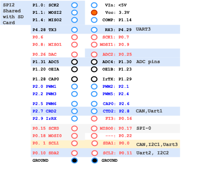
The LPC (SJ2) microcontroller has dedicated pins that can be used for serial communication such as UART. The uart3_init() or uart__init() code did not explicitly choose the UART pins to initialize the RX/TX. The first thing to do is identify the pins that you will be using (or compromising) for UART communication.
Please reference:
After selecting the UART pins from the article, you can use gpio__construct_with_function() API for initializing UART pins:
// UART1 is on P0.15, P0.16
gpio__construct_with_function(GPIO__PORT_0, 15, GPIO__FUNCTION_1); // P0.15 - Uart-1 Tx
gpio__construct_with_function(GPIO__PORT_0, 16, GPIO__FUNCTION_1); // P0.16 - Uart-1 Rx

// UART2 is on P0.10, P0.11
gpio__construct_with_function(GPIO__PORT_0, 10, GPIO__FUNCTION_1); // P0.10 - Uart-2 Tx
gpio__construct_with_function(GPIO__PORT_0, 11, GPIO__FUNCTION_1); // P0.11 - Uart-2 RX

// UART3 is on P4.28, P4.29
gpio__construct_with_function(GPIO__PORT_4, 28, GPIO__FUNCTION_2); // P4.28 - Uart-3 Tx
gpio__construct_with_function(GPIO__PORT_4, 29, GPIO__FUNCTION_2); // P4.29 - Uart-3 Rx
At this point, put your SJ2 board away, and perform test-driven development of the code modules and we will test it on the board at the last step of this lab. You can use the following sample code in conjunction by shorting the UART3 RX/TX pins to ensure that you can send and receive data correctly.
static char output_data = 'a';

void periodic_callbacks__1Hz(uint32_t callback_count) {
  uart__put(UART__3, output_data, 0);

  char input = 0;
  if (uart__get(UART__3, &input, 2)) {
    printf("Tx %c vs. Rx %c\n", output_data, input);
  }

  ++output_data;
  if (output_data > 'z') {
    output_data = 'a';
  }
}
Part 1: Create line_buffer code module
In this part of the lab, you will create a new code module that will remove data from the UART driver, and buffer it inside of this code module. Collaboration is encouraged so please pair the program and do not work on this code module alone. Notice the minimal API because according to our tests below, we simply will not need anything further than this.
#pragma once

#include <stdint.h>
#include <stdbool.h>

// Do not access this struct directly in your production code or in unit tests
// These are "internal" details of the code module
typedef struct {
  void * memory;
  size_t max_size;
  size_t write_index;
} line_buffer_s;

/**
 * Initialize *line_buffer_s with the user provided buffer space and size
 * Use should initialize the buffer with whatever memory they need
 * @code
 *  char memory[256];
 *  line_buffer_s line_buffer = { };
 *  line_buffer__init(&line_buffer, memory, sizeof(memory));
 * @endcode
 */
void line_buffer__init(line_buffer_s *buffer, void *memory, size_t size);

// Adds a byte to the buffer, and returns true if the buffer had enough space to add the byte
bool line_buffer__add_byte(line_buffer_s *buffer, char byte);

/**
 * If the line buffer has a complete line, it will remove that contents and save it to "char * line"
 * Note that the buffer may have multiple lines already in the buffer, so it will require multiple
 * calls to this function to empty out those lines
 *
 * The one corner case is that if the buffer is FULL, and there is no '\n' character, then you should
 * empty out the line to the user buffer even though there is no newline character
 *
 * @param line_max_size This is the max size of 'char * line' memory pointer
 */
bool line_buffer__remove_line(line_buffer_s *buffer, char * line, size_t line_max_size);
Here are the unit-tests that are already designed for you. You should use this to ensure that the line buffer code module is working correctly. These unit-tests are pre-written because we wanted to ensure that your line buffer module is functional even in the corner cases; feel free to also add more tests to these minimal set of tests.
#include "unity.h"

// Include the source we wish to test
#include "line_buffer.h"

// Most unit-tests focus on nominal cases, but you should also have
// tests that use larger line buffers etc.
static line_buffer_s line_buffer;
static char memory[8];

// This method re-initializes the line_buffer for the rest of the tests
void setUp(void) { line_buffer__init(&line_buffer, memory, sizeof(memory)); }

void tearDown(void) {}

static void add_bytes_to_buffer(const char *string) {
  for (size_t index = 0; index < strlen(string); index++) {
    TEST_ASSERT_TRUE(line_buffer__add_byte(&line_buffer, string[index]);
  }
}

void test_line_buffer__nominal_case(void) {
  add_bytes_to_buffer("abc\n");

  char line[8];
  TEST_ASSERT_TRUE(line_buffer__remove_line(&line_buffer, line, sizeof(line)));
  TEST_ASSERT_EQUAL_STRING(line, "abc");
}

void test_incomplete_line(void) {
  add_bytes_to_buffer("xy");

  char line[8];
  // Line buffer doesn't contain entire line yet (defined by \n)
  TEST_ASSERT_FALSE(line_buffer__remove_line(&line_buffer, line, sizeof(line)));

  // Line buffer receives \n
  line_buffer__add_byte(&line_buffer, '\n');
  TEST_ASSERT_TRUE(line_buffer__remove_line(&line_buffer, line, sizeof(line)));
  TEST_ASSERT_EQUAL_STRING(line, "xy");
}

void test_line_buffer__slash_r_slash_n_case(void) {
  add_bytes_to_buffer("ab\r\n");

  char line[8];
  TEST_ASSERT_TRUE(line_buffer__remove_line(&line_buffer, line, sizeof(line)));
  TEST_ASSERT_EQUAL_STRING(line, "ab\r");
}

// Line buffer should be able to add multiple lines and we should be able to remove them one at a time
void test_line_buffer__multiple_lines(void) {
  add_bytes_to_buffer("ab\ncd\n");

  char line[8];
  TEST_ASSERT_TRUE(line_buffer__remove_line(&line_buffer, line, sizeof(line)));
  TEST_ASSERT_EQUAL_STRING(line, "ab");

  TEST_ASSERT_TRUE(line_buffer__remove_line(&line_buffer, line, sizeof(line)));
  TEST_ASSERT_EQUAL_STRING(line, "cd");
}

void test_line_buffer__overflow_case(void) {
  // Add chars until full capacity
  for (size_t i = 0; i < sizeof(memory); i++) {
    TEST_ASSERT_TRUE(line_buffer__add_byte(&line_buffer, 'a' + i));
  }

  // Buffer should be full now
  TEST_ASSERT_FALSE(line_buffer__add_byte(&line_buffer, 'b'));

  // Retreive truncated output (without the newline char)
  // Do not modify this test; instead, change your API to make this test pass
  // Note that line buffer was full with "abcdefgh" but we should only
  // retreive "abcdefg" because we need to write NULL char to line[8]
  char line[8] = { 0 };
  TEST_ASSERT_TRUE(line_buffer__remove_line(&line_buffer, line, sizeof(line)));
  TEST_ASSERT_EQUAL_STRING(line, "abcdefg");
}
Part 2: Create gps code module
The GPS code module will glue the UART driver, and the line_buffer module and this will be the single module that needs to be integrated with the periodic callbacks.
The starter code for gps.h and gps.c is given below, but there are some missing pieces. This is not to spoil your fun, but to provide a guideline of how the GPS code module should be structured. You need to build the unit-tests for the GPS module: test_gps.c
// gps.h
#pragma once

// Note:
// South means negative latittude
// West means negative longitutde
typedef struct {
  float latitude;
  float longitude;
} gps_coordinates_t;

void gps__init(void);
void gps__run_once(void);

gps_coordinates_t gps__get_coordinates(void);
// gps.c
#include "gps.h"
// GPS module dependency
#include "uart.h"
#include "line_buffer.h"
#include "clock.h" // needed for UART initialization
// Change this according to which UART you plan to use
static const uart_e gps_uart = UART__2;
// Space for the line buffer, and the line buffer data structure instance
static char line_buffer[200];
static line_buffer_s line;
static gps_coordinates_t parsed_coordinates;
static void gps__transfer_data_from_uart_driver_to_line_buffer(void) {
char byte;
const uint32_t zero_timeout = 0;
while (uart__get(gps_uart, &byte, zero_timeout)) {
line_buffer__add_byte(&line, byte);
}
}
static void gps__parse_coordinates_from_line(void) {
char gps_line[200];
if (line_buffer__remove_line(&line, gps_line, sizeof(gps_line))) {
// TODO: Parse the line to store GPS coordinates etc.
// TODO: parse and store to parsed_coordinates
}
}
void gps__init(void) {
line_buffer__init(&line, line_buffer, sizeof(line_buffer));
uart__init(gps_uart, clock__get_peripheral_clock_hz(), 38400);
// RX queue should be sized such that can buffer data in UART driver until gps__run_once() is called
// Note: Assuming 38400bps, we can get 4 chars per ms, and 40 chars per 10ms (100Hz)
QueueHandle_t rxq_handle = xQueueCreate(50, sizeof(char));
QueueHandle_t txq_handle = xQueueCreate(8, sizeof(char)); // We don't send anything to the GPS
uart__enable_queues(gps_uart, rxq_handle, txq_handle);
}
void gps__run_once(void) {
gps__transfer_data_from_uart_driver_to_line_buffer();
gps__parse_coordinates_from_line();
}
gps_coordinates_t gps__get_coordinates(void) {
// TODO return parsed_coordinates
}// @file test_gps.c
#include "unity.h"
// Mocks
#include "Mockclock.h"
#include "Mockuart.h"
#include "Mockqueue.h"
// We can choose to use real implementation (not Mock) for line_buffer.h
// because this is a relatively trivial module
#include "line_buffer.h"
// Include the source we wish to test
#include "gps.h"
void setUp(void) {}
void tearDown(void) {}
void test_init(void) {}
void test_GPGLL_line_is_ignored(void) {}
void test_GPGGA_coordinates_are_parsed(void) {
const char *uart_driver_returned_data = "$GPGGA,hhmmss.ss,llll.ll,a,yyyyy.yy,a,x,xx,x.x,x.x,M,x.x,M,x.x,xxxx*hh\r\n";
for(size_t index = 0; index <= strlen(uart_driver_returned_data); index++) {
const char the_char_to_return = uart_driver_returned_data[index];
const bool last_char = (index < strlen(uart_driver_returned_data));
uart__get_ExpectAndReturn(UART__3, ptr, 0, last_char);
// TODO: Research on ReturnThruPtr() to make it return the char 'the_char_to_return'
}
gps__run_once();
// TODO: Test gps__get_coordinates():
}
void test_GPGGA_incomplete_line(void) {}
void test_more_that_you_think_you_need(void) {}
Part 3: Integrate and test
Once you have your GPS and line buffer code module fully tested, this part might be the simplest part because your code may simply work the first time (which usually never happens). This is of course only possible because you have already unit-tested your code.
Also note that when you integrate the GPS code modules to periodic_callbacks.c, you will need to also update the unit-tests for test_periodic_callbacks.c by adding the mock of gps.c
void periodic_callbacks__initialize(void) {
  // This method is invoked once when the periodic tasks are created
  gps__init();
}

/**
 * Depending on the size of your UART queues, you can probably
 * run your GPS logic either in 10Hz or 100Hz
 */
void periodic_callbacks__100Hz(uint32_t callback_count) {
  gpio__toggle(board_io__get_led2());
  gps__run_once();
}
One assumption is that the second SJ2 board is already interfaced to your primary SJ2 board and is sending fake GPS data (see the sample code below). You can alternatively loopback your own board's UART pins and send GPS string data while simultaneously receive your own data back to test the implementation.
// @file: fake_gps.c
#include "fake_gps.h" // TODO: You need to create this module, unit-tests for this are optional

#include "uart.h"
#include "uart_printf.h"

#include "clock.h" // needed for UART initialization

// Change this according to which UART you plan to use
static uart_e gps_uart = UART__1;

void fake_gps__init(void) {
  uart__init(gps_uart, clock__get_peripheral_clock_hz(), 38400);

  QueueHandle_t rxq_handle = xQueueCreate(4,   sizeof(char)); // Nothing to receive
  QueueHandle_t txq_handle = xQueueCreate(100, sizeof(char)); // We send a lot of data
  uart__enable_queues(gps_uart, rxq_handle, txq_handle);
}

/// TODO: You may want to be somewhat random about the coordinates that you send here
void fake_gps__run_once(void) {
   static float longitude = 0;
   uart_printf(gps_uart, "$GPGGA,230612.015,%4.4f,N,12102.4634,W,0,04,5.7,508.3,M,,,,0000*13\r\n", longitude);
   longitude += 1.15; // random incrementing value
}
Advanced Hints:
- You can use
queuemodule you built in the previous lab inside of yourline_buffer.hmodule- This means, that enqueue and dequeue logic would not have to be re-invented
- You can choose to decouple the GPS module from the UART
- The advantage would be to de-couple GPS code module from UART
- This would provide greater flexibility while unit-testing
- The glue logic of UART and GPS can occur at another code module. This can be tested separately and it would be easy to test because this module's job is simply to read data from UART and pass it on to the
gps__run_periodic()function
// GPS API modification
// run_periodic() can be designed to not read data over a concrete UART API
// Instead, we can choose to receive accumulated data as a parameter
void gps__run_periodic(const char *accumulated_data);

// At a different code module, you can "glue" GPS and UART
void gps_uart_glue__run_once(void) {
  char accumulated_data[200] = { 0 };
  get_accumulated_data_from_uart(accumulated_data, sizeof(accumulated_data));
  gps__run_periodic(accumulated_data);
}
LAB: CAN bus
Objective
- Get a practical experience with CAN bus communication
- Create hardware circuitry necessary for the CAN bus
You need to work with your lab partner in this lab. Be sure to pair the program, and not work independently on this lab.
Part 0: Interface two boards over CAN transceiver
CAN bus requires additional hardware that will be interfaced to your board. Your CAN controller has Rx and Tx wires, and these are interfaces to a "CAN Transceiver" which translates the Tx wire to the CAN bus line. Note that when this translation is performed, the CANH and CANL represent the state of the single Tx wire, and you are basically at half-duplex CAN bus. At any time, you are either transmitting or receiving, but you cannot be transmitting and receiving at the same time because CAN bus is a half-duplex bus. If you are actively transmitting, the Rx wire represents your own transmission that is read back from CANH and CANL.

Part 1: Configure the CAN driver
Reference the following starter code for details. To initialize the CAN driver, the easiest approach is to invoke the init() function and then bypass the CAN message acceptance filter and receive all CAN frames that arrive on the bus.
One thing you should do is that created a new code module such as can_bus_initializer.h Such that at the periodic_callbacks__initialize(), you invoke a single function to initialize the CAN bus. This would make it easier to add the unit-test for the periodic callbacks, and furthermore not create a blob software anti-pattern.
#include "can_bus.h"

void periodic_callbacks__initialize(void) {
  // TODO: You should refactor this initialization code to dedicated "can_bus_initializer.h" code module
  // Read can_bus.h for more details
  can__init(...);
  can_bypass_filter_accept_all_msgs(...);
  can_reset_bus(...);
}
Part 2: Send and Receive messages
Setup your code in a 10 or 100Hz task:
- Transmit a test message
- Receive all messages enqueued by your CAN driver
- This would empty out all messages you received, not including the message you transmitted
Reference the following starter code for details. Once again, you should actually create a new code module called can_bus_message_handler.h. This file is definitely expected to grow because you will be handling a lot more CAN message in your RC car's production code.
#include "can_bus.h"

// DONT
void periodic_callbacks__100Hz(uint32_t callback_count) {
  // TODO: Send a message periodically
  can__tx(...);

  // Empty all messages received in a 100Hz slot
  while (can__rx(...)) {

  }
}

// DO
void periodic_callbacks__100Hz(uint32_t callback_count) {
  can_handler__run_once();
}
Be careful of the following:
- Since your periodic callback of 100Hz expects your function to return within 10 ms, you cannot block while receiving data from the CAN bus
Part 3: Simple CAN bus application
- Build a meaningful communications' application
- For example, if Board=A senses a switch pressed, then send a 1-byte message with 0xAA, otherwise, send 0x00 if a button is not pressed
- On Board-B, simply light up an LED (or otherwise turn it off) based on the CAN message data
- For robustness, if the CAN Bus turns off, simply turn it back on at 1Hz (every 1000 ms)
- You can be more creative here by sending tilt sensor readings from one board to another board and should have the mindset to go "above and beyond"
Conclusion
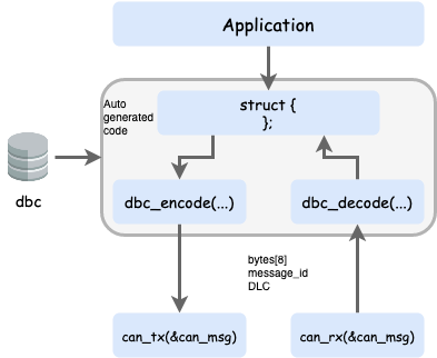
This assignment gives you an overview of the practical use of the CAN Bus, and later, by utilizing the DBC file and auto-generation of code, sending and receiving data becomes very easy.
While this provides bare-bones knowledge of how communication works, the future lectures will focus on the application layer while abstracting away the details of CAN messages' data encoding and decoding.
Be sure to submit a Merge Request of your Git repository to get credit for the assignment.
LAB: CAN bus with DBC

Objective of this lab is to:
- Define CAN message types in a DBC file
- Auto-generate code based on the DBC file
- Use two SJ2 boards interfaced over the CAN bus to communicate using generated code
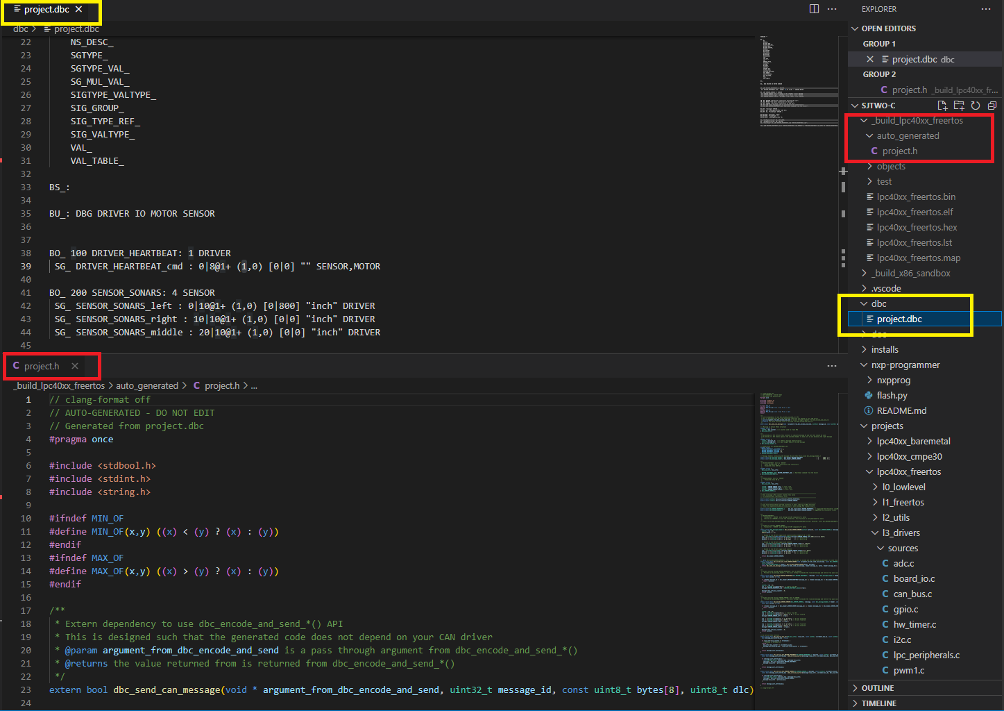
Part 0: DBC File
In this part, we will give meaning to various different bits and bytes that will be sent over the CAN bus. We are giving you a reference of MOTOR_CMD message, and in the sample dbc file located in your project folder, there is also project.dbc. These are reference points only, and you should be creating your own DBC message and not use these references word by word.
The snippet below dictates the following and you can read about DBC files in detail here. Documentation about the code generation can be referenced here.
- A message with ID
100(decimal) will be sent and the name isMOTOR_CMD - This message will only be composed of a
1data byte - It is sent by a CAN bus node called the
DRIVER - First data field is
MOTOR_CMD_steerand it is a 4-bit field starting with bit 0- Intention is to send data in the range of -5 to +5
- Second data field is
MOTOR_CMD_drive- We designed this field to represent numbers between 0-9 as in 0 for stop, and 9 for highest speed
- The two data fields are received by a CAN bus node called the
MOTOR- There can be multiple receives separated by a comma, such as
MOTOR,IO
- There can be multiple receives separated by a comma, such as
BO_ 101 MOTOR_CMD: 1 DRIVER
 SG_ MOTOR_CMD_steer : 0|4@1+ (1,-5) [-5|5] "" MOTOR
 SG_ MOTOR_CMD_drive : 4|4@1+ (1,0) [0|9] "" MOTOR
Use the references and create your own message composed of "signals" that you wish to send from one microcontroller to another. We recommend that you create signals such as acceleration sensor value, or a button press value that you will send from one board to another.
Create your DBC
- Reference Part 4 and think about messages you will send between microcontrollers interfaced over the CAN bus. This could be acceleration sensor readings, or light sensor values.
- After you decide what data to transfer between controllers, think about the node names and add them to the BU line:
BU_: DBG DRIVER IO MOTOR SENSORat your DBC file
Part 1: Code Generation
In this part, we will auto-generate C code based on the DBC file. The significance is that we want to minimize code development that is responsible to send correct data set on the CAN bus. This not only removes the tedious work and allows the developers to focus on the CAN application, but also minimizes common bugs related to transmission of data on the CAN bus.
An important aspect of code generation is that you should not have an API that is not relevant for your CAN node. So if you are the DRIVER CAN node, then you should not have functions that are related to sending sensor values of the SENSOR CAN node. To accomplish this, from now on, you should be using the following to compile your code
-
scons --dbc-node-name=<node name>- Example:
scons --dbc-node-name=MOTOR - The node name should be one of the ones defined in your DBC file:
BU_: DBG DRIVER IO MOTOR SENSOR
- Example:
- This ensures that you will not generate any code that is not relevant for your CAN node
- The default behavior is that code is generated for "ALL" nodes, which is not something you should do and it should be used for purely test purposes only. Another positive side effect is that when the DBC gets bigger, you want to read the code that is only relevant for yourself.
Study Generated Code
Please read the README.md file located in your project directory (or click here) to better understand the code generation aspect. Stop here, and spend 1-2 hours to understand the generated code that was created from your dbc file. We really mean it... spend time understanding the code because on the exams you will be asked to write this "encode" and "decode" code by yourself.
Unit Testing
For the code modules that use auto-generated code, you should not mock the generated code header file. This is because this is trivial code that does not involve any other code dependencies, and it is better to unit-test your code modules that use the auto-generated code without mocking. That means that in your unit-test file, simply #include the generated code, and let it encode and decode messages like it normally would.
Part 2: MIA Integration
In this part, we will provide instances of two key data types:
- MIA counter threshold to replace data structure instance
- MIA data structure instance itself
Well of course, we have to understand what is "MIA". MIA is Missing-In-Action, and the idea is that when an expected periodic message has not arrived, we replace it with safe values. For instance, when a temperature reading has not arrived, we can set the ambient temperature as a replacement value. This way, we do not have to repeatedly check if we can trust data values. In other words, if your RC car is controlling motors, we want to avoid this type of code:
void drive_motors(void) {
  if (!sensor_values_are_valid()) {
    motor_speed_percent = 0;
  } else {
    if (sensor > 40) {
      motor_speed_percent = 10;
    } else {
      motor_speed_percent = 0;
    }
  }
}
The code snippet above demonstrates that our code will be cluttered if we have to check for its validity everywhere. Instead, when periodic data goes missing, we just replace with zero, and therefore we can just retain this logic without checking for data validity upon each access of CAN network data.
void drive_motors(void) {
  if (sensor > 40) {
    motor_speed_percent = 10;
  } else {
    motor_speed_percent = 0;
  }
}
Take a note of the following auto-generated code which is asking for extern definitions from you:
// -----------------------------------------------------------------------------
// When a message's MIA counter reaches this value
// corresponding MIA replacements occur
// -----------------------------------------------------------------------------
extern const uint32_t dbc_mia_threshold_MOTOR_STATUS;

// -----------------------------------------------------------------------------
// User must define these externed instances in their code to use MIA functions
// These are copied during dbc_decode_*() when message MIA timeout occurs
// -----------------------------------------------------------------------------
extern const dbc_MOTOR_STATUS_s         dbc_mia_replacement_MOTOR_STATUS;
You will have to define the extern data values in a code module such as can_mia_configurations.c You can choose your own MIA replacement values, but if you leave it un-initialized they may be assumed as zero due to ANSI C standards.
// @file can_mia_configurations.c

const uint32_t dbc_mia_threshold_MOTOR_STATUS = 500; // 500ms

// Leave uninitialized if we wish to accept zero values as sane MIA replacement
const dbc_MOTOR_STATUS_s dbc_mia_replacement_MOTOR_STATUS;
Handle your MIA
After defining the data above in a file such as can_mia_configurations.c, invoke the MIA management in one of your periodic functions like so:
// @file periodic_callbacks.c
void periodic_callbacks_10hz(void) {
  can_handler__manage_mia_10hz();
}

// @file can_handler.c
void can_handler__manage_mia_10hz(void) {
  // We are in 10hz slot, so increment MIA counter by 100ms
  const uint32_t mia_increment_value = 100;

  if (dbc_service_mia_MOTOR_STATUS(&can_msg__motor_status, mia_increment_value))) {
    // Take action when a message has gone MIA?
    // Maybe light up an LED?
  }
}
Part 3: Encode and Decode
Encoding is used when you wish to transmit a data structure to the CAN bus. Obviously, this should only be used for a message that you are a transmitter of. Remember that no two nodes shall transmit the same message on a CAN bus. For more details about the auto-generated DBC API, see the following examples: Exploring DBC Autogenerated API.
// @file can_handler.c

// We are assuming that we have a 10hz function in which we wish
// to transmit all messages that should be sent at 10x per second
void can_handler__transmit_messages_10hz(void) {
  // Realistically, this message should be populated by a dedicated code module
  // TODO: Populate dbc_SENSOR_SONARS_s struct members
  dbc_SENSOR_SONARS_s sensor_struct = {};

  // Encode struct to bytes of the CAN message
  can__msg_t can_msg = {};
  const dbc_message_header_t header = dbc_encode_SENSOR_SONARS(can_msg.data.bytes, &sensor_struct);

  can_msg.msg_id = header.message_id;
  can_msg.frame_fields.data_len = header.message_dlc;
  can__tx(can1, &can_msg, 0);
}
On the receiving side, you should empty out all CAN frames received from the CAN driver, and then handle it in sort of a brute force approach.
// @file can_handler.c

void can_handler__handle_all_incoming_messages(void) {
  can_msg_t can_msg = {};
  dbc_MOTOR_CMD_s decoded_motor_cmd = {};

  while (can__rx(can__1, &can_msg, 0)) {
    // Construct "message header" that we need for the decode_*() API
    const dbc_message_header_t header = {
      .message_id = can_msg.msg_id,
      .message_dlc = can_msg.frame_fields.data_len,
    }

    // Even if incoming message is NOT motor cmd, our decode functions
    // will gracefully handle it because we provide valid "message header"
    dbc_decode_MOTOR_CMD(&decoded_motor_cmd, header, can_msg.data.bytes);
  }
}
And, don't forget MIA management of the message as mentioned in the section above.
Part 4: CAN Application
In this part, we will focus on the CAN based application. In particular, a controller will send sensor data information on the CAN bus, and another controller will receive the data, interpret it, and print it out.
Summary of your overall tasks:
- Define a DBC message for some data you wish to send
- Use Board #1 to encode and transmit the data periodically
- Use Board #2 to decode the received frame and do something with the received data
- And of course, be creative
Part 5: BusMaster
In this part, you will connect your CAN bus over a PCAN dongle, and view your data on "Bus Master" which is an open source program to view CAN bus messages. You will connect the PCAN dongle over to a DB9 connector that is connected to your CAN bus.
Follow this link and setup your Bus Master, and follow the steps to install, configure, and explore the program.
Final Requirements
- New message added in DBC
- Encode and Decode use the generated code based on the DBC
- Demonstration of the MIA (light up LED when message is missing)
- Unit-tests of the new code modules
- Demonstration of your CAN messages also appearing in the BusMaster
Unit Test Hints
TODO
LAB: RC Car Infrastructure
We are now on a roll . . . we are now going to work with multiple controllers that are interfaced to the CAN bus and react to each other's data. Please be sure to read this article.
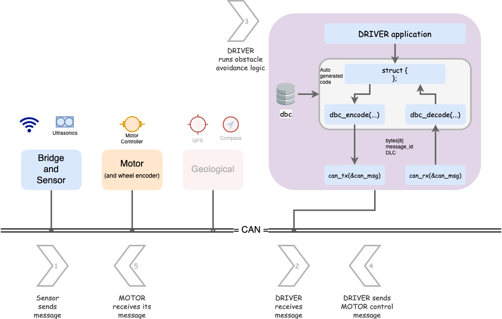
In this lab, we are going to setup basic building blocks of your autonomous RC car. Here is a required article you should read first. The outcome of the assignment is potentially multiple Gitlab Merge Requests MR - one for each controller. You will not only be setting up controllers that are communicating and reacting to data, but will also use BusMaster to demonstrate your data graphs of the CAN messages.
- Driver node
- Handles received CAN messages from the Sensor node
- Sends commands to the Motor Controller node
- Sensor node sends out sensor messages
- Optional to add real sensors, otherwise we suggest an incremeting distance sensor value sent on the CAN bus
- Feel free to add debug counters, something as simple as the 1Hz callback count
- Optional to add real sensors, otherwise we suggest an incremeting distance sensor value sent on the CAN bus
- Motor Controller node that receives commands
- Optional to add real servo (or motor) controller
- Feel free to add debug counters, something as simple as the 1Hz callback count
This will be a RC car GROUP assignment, meaning multiple MRs for your larger RC car team.
- Driver node will have most of the code, which will intercept Sensor node messages and send Motor controller commands
- Sensor node will at minimum send some kind of sensor values (could be fake ones)
- The Motor Controller code is simple and doesn't need to do much other than receive its motor commands CAN message from the Driver node.
Part 0: DBC
In this part, you should define the following CAN messages in the DBC file:
- Sensor node messages
- Transmit: At minimum, front, left, and right sensor reading (usually ultrasonic distance sensor)
- Motor Controller node messages
- Receive: Steer and wheel control messages (transmitter will be Driver node)
- Driver node messages
- Transmit: Steer and wheel control messages
- Potentially debug information because you will receive Sensor node message(s) and transmit to Motor Controller node
Remember YAGNI, do not over-engineer things. Invent minimal DBC and code because there will be less code to write, less code to test. Do not solve for theoretical problems until you really see them. We would encourage you to have your steering values between -2 to +2 and wheel speed as kph with fraction of 0.1
Part 1: Driver Obstacle Avoidance Code Module
Design your code modules with simple input, and output as your first preference. Simple I/O modules are easier to code and test for. For example, the driver code module should be like the following:
// @file driver_logic.h

// Assuming this data structure as input from the DBC
struct dbc_SENSOR_data_s;

// Assuming this data structure as output from the DBC
struct dbc_MOTOR_command_s;

// This should copy the sensor data to its internal "static" struct instance of dbc_SENSOR_data_s
void driver__process_input(dbc_SENSOR_data_s sensor_data);

// This should operate on the "static" struct instance of dbc_SENSOR_data_s to run the obstacle avoidance logic
dbc_MOTOR_command_s driver__get_motor_commands(void);

/**
 * Wow...
 * Is our Driver really going to be that simple? --> Yes, you should at least try to keep it that way.
 *
 * It takes a lot of effort to solve problems with minimal code
 * It is easy to write more code, and appear to be busy solving nasty intertwined bugs
 *
 * Yes, it is true that when you add GPS heading, your driver logic will change,
 * but we can work on that after this stage
 */
Part 2 gives suggestion regarding which code module should be invoking the driver__process_input() function.
Part 2: Handle CAN
Code modules like driver_logic.h should not be dealing with the CAN driver. All this code module should say is that "give me sensor values and I will give you back motor commands". This is part of modularizing code, and the path to not create The Blob.
Let us create a dedicated code module to handle arriving CAN messages
// @file msg_bank.h
#include "can_bus.h"

// Invoke this method in your periodic callbacks
void msg_bank__handle_msg(const can_msg_t *message);

// MIA management:
void msg_bank__service_mia_10hz(void);

// "GET" APIs to obtain latest data
dbc_SENSOR_data_s msg_bank__get_sensor_data(void);
dbc_some_data_s msg_bank__get_other_data(void);
// @file msb_bank.c
// Include code modules that should receive their decoded CAN messages
#include "driver_logic.h"
#include "another_code_module.h"
static dbc_SENSOR_data_s sensor_data = {};
static dbc_some_data_s some_data = {};
void can_bus_handler__process_all_received_messages(void) {
can_msg_t can_msg = {};
// Receive all messages
while (can_rx(can1, &can_msg)) {
const dbc_message_header_t header = {
.message_id = can_msg.msg_id,
.message_dlc = can_msg.frame_fields.data_len,
}
if (dbc_decode_sensor_data(&sensor_data, header, can_msg.data.bytes)) {
}
if (dbc_decode_some_data(&some_data, header, can_msg.data.bytes)) {
}
}
}The testing of the can_bus_handler.c should be easy because all it does is decodes messages, and routes the data to the code module owners. You can either have can_rx_StubWithCallback() or use can_rx_ReturnThruPtr() variants to carry out your unit-tests.
Part 3: Handle CAN transmit
The driver_logic.h processed incoming data, and ran its algorithm to compute the motor and wheel commands. we also need to send the CAN messages out.
The following approach is suggested and please reference this article on the encode_and_send() API variant.
// @file can_bus_handler.h
#include "can_bus.h"

// Maybe at 10Hz, send the motor commands
void periodic_callbacks_10Hz(void) {
  // TODO Fix this
  const dbc_MOTOR_command_s command = driver__get_motor_commands();

  // Encode and send the CAN message
  dbc_encode_and_send(&command);
}
If you define dbc_send_can_message() then it can provide convenience of sending the CAN messages:
void can_bus_handler__transmit_messages(void) {
  // TODO Get struct to send from driver_logic.h

  // This function will put everything together and invoke dbc_send_can_message() internally
  // This avoids us having to re-construct CAN message data structure repetitively
  dbc_encode_and_send_DBC_TEST2(NULL, &dbc_MOTOR_commands);
}

// define this at maybe dbc_to_can_driver_glue.c
bool dbc_send_can_message(void * argument, uint32_t message_id, const uint8_t bytes[8], uint8_t dlc) {
  can_msg_t msg = {};

  msg.frame_fields.dlc = dlc;
  msg.message_id = message_id;
  memcpy(msg.data.bytes, bytes, 8);

  return can_tx(can1, &msg, 0);
}
Part 4: BusMaster Debugging
In this part, you will use BusMaster to demonstrate:
- Graphical view of the sensor message
- A common graph where you can plot motor command with respect to sensor messages
Conclusion
For the Merge Requests, we expect that you:
- Demonstrate code modules, with unit tests
- Build the DRIVER node logic that receives messages, and transmits motor controller message
- Build the SENSOR node that sends sensor data
For the BusMaster portion, we expect that you:
- Open DBC file in BusMaster
- Design a simple GUI or graphs in BusMaster that demonstrates that as the SENSOR node distance data slowly increments, the motor controller commands make reasonable decision
- Impress the ISA team
LAB: Geo Controller
In this lab, we will add the Geological Controller to your RC car. Please review this article to figure out the roles and responsibilities of different controllers in your RC car.
The high-level idea is that:
- Geo Controller receives a destination in the form of latitude and longitude
- Geo Controller also has a link to the GPS module
- You can more or less use the Pythagorean theorem to compute the heading degree for the Driver Controller
This will take some research but the earth is not flat (it is really not flat), and so if you use the Pythagorean theorem, your heading degree may not be fully accurate, but it will work on the scale of your RC car unless you are sending it long distance such as US to Canada.
Another research item is that you will have to eventually align your GPS degree to the Compass degree. For example, your compass degree may have 90 degrees as North, whereas your GPS may or may not agree, but for this lab, we can assume fake values of the compass and focus only on the GPS portion. When you eventually fix this logic, no other controller would need to know because they are abstracted away as they only focus on the destination and current heading, and how you compute these numbers is not a concern for other controllers as long as you do it right.
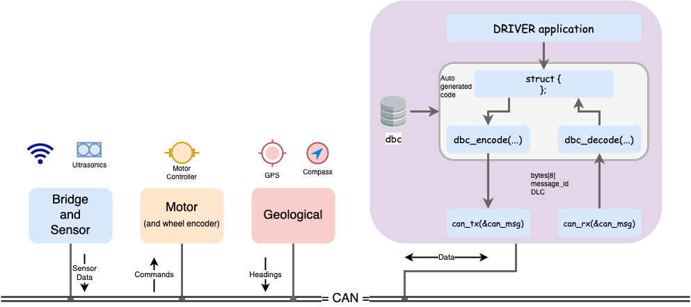
Part 0: DBC
In this part, you should define the following CAN messages in the DBC file:
- GPS destination message
- The Bridge Controller should send the destination to Geo Controller
- This should include longitude(float) and latitude (float).
- Assign the number of bytes and change the range as per your requirement.
DBC Example 1 for GPS destination message:
BO_ ID GPS_DESTINATION_LOCATION: 8 TX_NAME
 SG_ GPS_DEST_LATITUDE : 0|28@1+ (0.000001,-90.000000) [-90|90] "Degrees" RX_NAMES
 SG_ GPS_DEST_LONGITUDE : 28|28@1+ (0.000001,-180.000000) [-180|180] "Degrees" RX_NAMES
DBC Example 2 for GPS destination message:
In this example, it would help you get around the fact that a "float" is only a 32-bit imprecise number. More particularly, it cannot host a decimal precision past 6 decimals. Furthermore, if the significant number increases (such as 0.123 to 123.123), then the decimal precision may be reduced below 6 decimals.
In order to effectively send high precision numbers, you can scale them manually. So if you wanted to send 123.012345, then you can manually send the number as 123012345.
BO_ ID GPS_DESTINATION_LOCATION: 8 MOBILE_APP
 SG_ GPS_DEST_LATITUDE_SCALED_100000 : 0|32@1- (1,0) [0|0] "Degrees" RX_NAMES
 SG_ GPS_DEST_LONGITUDE_SCALED_100000 : 32|32@1- (1,0) [0|0] "Degrees" RX_NAMES
2. Compass heading and distance message
- The Geo Controller should send this message to the LCD or Bridge Controller
- Include 0-360 degrees of current heading(after using haversine formula) and the bearing angle(optional) (from the Compass)
- Include the distance to the destination in meters in order to update the real-time remaining distance on the mobile application.
- Assign the number of bytes and change the range as per your requirement.
DBC Example for the compass heading and distance message:
BO_ 100 GEO_STATUS: 8 TX_NAME
  SG_ GEO_STATUS_COMPASS_HEADING : 0|12@1+ (1,0) [0|359] "Degrees" RX_NAMES
  SG_ GEO_STATUS_COMPASS_BEARING : 12|12@1+ (1,0) [0|359] "Degrees" RX_NAMES
  SG_ GEO_STATUS_DISTANCE_TO_DESTINATION : 24|16@1+ (0.1,0) [0|0] "Meters" RX_NAMES
Part 1: Driver Obstacle Avoidance Code Module
Remember our last code module for the driver? We will extend it to also absorb the Geo Controller message, and then we will use this information to figure out the motor controller commands.
// @file driver_logic.h

// Assuming these data structures from the generated DBC
struct dbc_SENSOR_data_s;
struct dbc_MOTOR_command_s;
struct dbc_GEO_status_s;

// This should copy the sensor data to its internal "static" struct instance of dbc_SENSOR_data_s
void driver__process_input(dbc_SENSOR_data_s sensor_data);
void driver__process_geo_controller_directions(dbc_GEO_status_s geo_status);

// This should operate on the "static" struct instance of dbc_SENSOR_data_s to run the obstacle avoidance logic
dbc_MOTOR_command_s driver__get_motor_commands(void);
Part 2: The power of TDD
The beauty of unit-tests is that when we add additional logic, we can still ensure that our previously written code is not going to break or malfunction. The Geo Controller message should have no impact on the output of the motor controller commands if there is an obstacle avoidance actively being used. Only if all sensors show that there is no obstacle should your RC car obey the Geo Controller commands, and steer the car in the right direction.
Please ensure that your existing unit tests pass, and then add the additional logic necessary to handle the steering angle based on the Geological controller's status message (compass headings).
Part 3: Extras
You should invest in easy diagnostic functionality, so slap on a couple of bright LED indicators (driven by a higher current transistor or MOSFET) to indicate things such as:
- An obstacle is in the near vicinity and GPS heading is not being followed
- This will tell you if the RC car is following the GPS or avoiding an obstacle
- A ring LED device that indicates where the RC car is trying to go
- Sparkfun device link may be non-trivial to drive this LED device but should be worth the effort
While this part is technically "extra credit", implementing these kinds of easy features will save you a ton of time later in the project.
Class Project and Useful Articles
Project Introduction and Guidelines
Shopping List
- Four SJtwo Development Kits + 4 CAN Transceivers
- Bridge and Sensors Accessories - Bluetooth or Wifi Breakout Board and Ultrasonic Sensors
- Motor Controller Accessories - RPM Sensors
- GEO Controller Accessories: GPS Breakout Board, Compass, GPS Antenna
- Extra LCD and LEDs for visual effects.
- Mechanical - RC Car, RC CAR Battery charger, Lithium-Ion Battery
- PCB parts and other Miscellaneous parts for Hardware.
Controllers
Various different controllers are used and each should have limited and exclusive responsibilities. Use this article as a reference to derive your project schedule and individual team member tasks.

An example of how GPS coordinates are sent from the Mobile phone:
- Mobile phone sends data as ASCII text to the Bridge
- The bridge controller receives information over UART
- The bridge controller sends data using DBC/CAN to the Geological
- No other controller should need to know the destination coordinates because the Geological controller will guide the Driver controller with its compass heading, and tell it to stop when necessary
Suggested Roles
- Mobile application development
- 3+ General developers (could be dedicated developer per controller or just collaborative effort)
- Testing and Integration person (2 people who can work together)
1: Bridge and Sensor Controller
Requirements
- Shall be interfaced to all of the distance sensors
- Note that your board only has 3 ADC channels if you choose to use this interface
- Note that ultrasonic sensors can collide in their sound waves and interfere with each other. It may be better to use different frequency based sensors (maybe different vendor or models) to minimize the interference.
-
Shall output all sensor information with a minimum refresh rate of 20Hz
- Shall provide the interface (such as Bluetooth serial) to a mobile application running on a phone
- The typical interface to a Bluetooth or Wifi is UART
- Bluetooth requires pairing and is usually stable after that
- Wifi would require your wi-fi to act as an access point for your mobile phone to
- Both interfaces should work, and you can pick one based on past semesters' reports
- A recommendation is that a Mobile phone sends a line of command terminated by a newline, and then the Bridge controller can parse the information (such as using scanf)
- Required but low priority:
- Provide battery voltage reading to Mobile Application and possibly to the DRIVER to output on the LCD
2: Motor Controller
Requirements
- Shall be interfaced with speed sensors or wheel encoders to provide speed information
- This should be transmitted on the CAN bus as either kph or mph; usually, the units will be small and you could use DBC scale of
0.001or0.01
- This should be transmitted on the CAN bus as either kph or mph; usually, the units will be small and you could use DBC scale of
- Shall be interfaced to motor controllers (or servo controller) to control steering and speed
- Recommend hobby grade RC car (such as Traxxas), and not a $20 RC car from Amazon
- Provide self-test capability button
- Self-Test pressed, so Driver controller should be commanded to a 5 seconds wheel test mode
- This should include forward, backward motion, and steering test
- Shall process the speed command, and compensate for the grade of the ground (uphill or downhill)
- For example, the DRIVER may command 0.5 kph, and the motor controller should process the wheel encoder and use a simple PID control loop to match the command regardless of the grade or battery power
3: Geological Controller
Requirements
- Shall be interfaced to a magnetometer
- Shall be interfaced with a GPS
- Shall provide raw GPS and compass readings
- Shall have the ability to "set destination" and then provide heading degree towards destination
- The driver controller should not need to get involved in GPS data. It should simply receive a compass destination heading, and an actual compass heading. When there is no obstacle, it should simply try to take its current heading towards the destination, heading (which is just a compass degree)
- Shall have the waypoints algorithm
4: Driver and LCD Controller
Requirements
- Shall be interfaced to an LCD display to output meaningful and diagnostic information
- Sensor values commanded motor values etc.
- A Recommendation is to use a simple UART or I2C based LCD
- Something like this
- Shall receive all relevant sensor messages and process them for obstacle avoidance
- Shall receive compass actual degree, and heading degree (towards the destination)
- Shall have the obstacle avoidance algorithm
- In the absence of any obstacles, it shall use the compass to follow the GPS destination
- Shall send output drive commands to the Motor Controller
5: Mobile Application
Requirements
The definite article More (Definitions, Synonyms, Translation)
Focus
There are different domains in your project that we need to ensure are working very robustly.
1. Distance Sensors
One person should focus solely on ensuring that VERY reliable values are being output from the sensor controller at least at 20Hz. Consider the following test case scenarios:
- Smoke tests: Test values while stationary
- Interference tests: With a known test scenario (such as blocking one side), are the sensor values stable? For example, if we are blocking only the right side, is the left sensor value still stable?
- Test on a moving car: Are the sensor mounts stable? Are the sensors pivoted downwards such that the floor is appearing to be an obstacle?
- There are many more test scenarios but the overall objective is to ensure that sensors are very reliable.
2. Compass
- Test in stationary vehicle
- Test while vehicle is moving
- Does the tilt of the vehicle make a big difference?
- Test while moving the front motor
- Test while moving the rear motor
- Test while moving both motors
- Is there magnetic interference?
3. Motor and wheel encoder
- Test with varying battery voltage
- Test with different speed command and ensure RPM consistency
The rest is mainly more and more testing, but there should be a systematic approach to this.
Project Hints
Git strategy to share common DBC file
A common issue for everyone is how to have separate projects in your Git repo.
- One option is to create a different folder, one for each project
- Maybe have a top-level DBC file, and manually copy to all other folders upon update
- Maybe infrastructure code can find the DBC file at the root level directory itself? This might be a simple modification in the Python-based scons script
- Another option is to use different Git branches
- Single folder for your project, such as lpc40xx_freertos but different "virtual" master branches
git checkout master_drivergit checkout master_sensor- The "master" branch is where the DBC is at, so when people want to get the latest, what they do is:
git checkout master_drivergit checkout mastergit pull origin mastergit checkout master_drivergit rebase mastergit push origin head
How can you nest an external repository's DBC file in your project repository.
- Git submodule
- Your DBC can live in a completely separate repo, maybe this repository is nothing but a single DBC file
- You can nest this external git submodule as a folder inside your lpc40xx_freertos directory
- So if someone changes the DBC file at the dedicated dbc repo, then everyone needs to update it
- git checkout master
- cd dbc_directory (nested git submodule)
- git pull origin master (of the external dbc repo, this will pull in the latest changes from there)
- cd - (step outside of the nested git submodule)
- git add dbc_directory (you update the githash that are pointing to the external repo's commit)
- git commit -m "update dbc"
- git push origin head
Motor Control
It is advised to have a state machine to move your car, such as forward, forward to reverse and reverse to forward.
void motor__run_state_machine_10hz(int call_counter) {
 switch (current_state) {
  case forward:
    if (desired_movement == reverse) {
      current_state = transient_state;
    }
    break;

  case transient_state:
    if (entry_to_this_state) {
      transient_state_entry_counter = call_counter;
    }

    if (call_counter >= (transient_state_entry_counter + 5) { // 500ms elapsed
      if (desired_movement == reverse) {
        current_state = reverse;
      } else {
        // ...
      }
    }
    break;

  case reverse:
    // ...
 }
}
Simple PID
The motor controller should use a simple PID to control the motors.
// return percentage 0-100 which then may need to be translated to the Servo PWM
float motor_pwm_1hz(float actual_speed_kph, float target_speed_kph) {
  // Also handle the case of deceleration or a complete stop
  if (0 == target_speed_kph) {
    return 0;
  }

  // Handle other cases
}
Receive CAN in only one function
Students oftentimes tend to try to handle CAN frame reception in multiple functions. The problem is that this creates a non-deterministic operation as some frames may be dropped in one place in code, and may not be handled where you really mean to handle them.
Note the following properties:
- A while loop to empty out the CAN receive queue
- Handling just one frame per function call will accumulate CAN frames leading to data loss
- After creating a message header, call all decode functions
- Only one decode function will decode at most since the message header will match only once
- This reduces your testing effort as you do not need manual switch/case statements
void can_handle_all_frames(void) {
    while (can_rx(...)) {
      msg_hdr = create_msg_header();

      dbc_decode_...();
      dbc_decode_...();
    }
}
Test I2C Sensor
If you have a sensor such as a compass that operates using I2C, then it is advised to use the built-in I2C CLI command on your SJ2 board to test out the sensor registers. Make sure you run the CLI task in your main.c and then simply type "help i2c" to explore the CLI command and trial the sensor data.
If the compass is interfaced on I2C and the slave address of the compass is 0x38. Then you can read a particular register using the CLI command i2c read SLAVE_ADDRESS REGISTER_ADDRESS <n>

Similarly, you can directly use the CLI to write the value to a particular register address of Compass by using i2c write SLAVE_ADDRESS REGISTER_ADDRESS VALUE
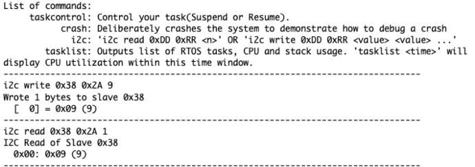
Transmit GPS coordinates in between controllers
Use the following DBC design:
BO_ 201 GPS_DESTINATION: 4 BRIDGE_CONTROLLER
 SG_ GPS_DESTINATION_LONGITUDE : 0|32@1+ (0.000001,0) [0|0] "" GEO_CONTROLLER
Be sure to keep in mind:
- A GPS coordinate is usually only sent with six decimal places maximum
- A
float, is always a 32-bit float (IEEE standard) - A
floatcan only store up to 6 decimal points- However, if your number changes from
0.123456to456.123456, then the precision is actually lost, and the number may actually be truncated to this:456.123444
- However, if your number changes from
More things to keep in mind:
- float is supported by HW on the ARM CM-4
- But a "double" uses software floating-point instructions
Checkpoints Algorithm
The algorithm should not be overcomplicated, and the checkpoints can just be static const array in your code.
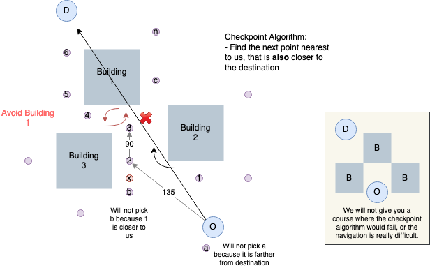
Keep in mind:
- Mobile application should only send the destination, and not these checkpoints
- The Geo controller has the pre-mapped, constant points in the compiled ARM CPU code
// Probably already defined in your *.h file
typedef struct {
  float long;
  float lat;
} gps_coordinates_t;

// Define in your *.c file
static const gps_coordinates_t locations_we_can_travel[] = {
  {a, b},
  {c, d},
  {e, f},
  {g, h},
}

/**
 * Algorithm should iterate through all locations_we_can_travel[] and find:
 *  - Another point that is closest to origin
 *  - while also simultaneously closer to the destination at the same time
 *
 * Corner case: If next point is the destination itself, which is also possible
 *.             and in this case, you should flag that destination has been reached
 */
gps_coordinates_t find_next_point(gps_coordinates_t origin, gps_coordinates_t destination);
Unit Testing code that touches the HW registers
This article guides you on how to unit-test code that reads or writes hardware registers of your SJ development board.
// Typical code
int get_ultrasonic_pulse_width(void) {
  // Send a pulse width
  LPC_GPIO1->CLR = (1 << 2);
  delay_us(10);
  LPC_GPIO1->SET = (1 << 2);

  const uint32_t previous = time_now();
  while (LPC_GPIO1->PIN & (1 << 3)) {
   ;
  }

  return time_delta(previous);
}
Before we solve the problem, let us write better code that is self expressive and does not require comments to understand its intent.
static void send_pulse_to_ultrasonic(void) {
  const uint32_t ultrasonic_pulse_pin = (1 << 2);

  LPC_GPIO1->CLR = ultrasonic_pulse_pin;
  delay_us(10);
  LPC_GPIO1->SET = ultrasonic_pulse_pin;
}

static void wait_for_ultrasonic_pulse_to_bounce_back() {
  while (LPC_GPIO1->PIN & (1 << 3)) {
   ;
  }
}

// Notice the clarity of this function compared to the previous code snippet
int get_ultrasonic_pulse_width(void) {
  send_pulse_to_ultrasonic();

  const uint32_t previous = time_now();
  wait_for_ultrasonic_pulse_to_bounce_back();
  return time_delta(previous);
}
And the next level:
// Separate header file to abstract the hardware, such that we can mock out this API
// file: ultrasonic_pins.h
void ultrasonic_pins__set_pulse(bool true_for_logic_high);
bool ultrasonic_pins__get_input_pin_value(void);
#include "ultrasonic_pins.h"
static void send_pulse_to_ultrasonic(void) {
// This can now move to ultrasonic_pins.c
// const uint32_t ultrasonic_pulse_pin = (1 << 2);
ultrasonic_pins__set_pulse(true);
delay_us(10);
ultrasonic_pins__set_pulse(false);
}
static void wait_for_ultrasonic_pulse_to_bounce_back() {
while (ultrasonic_pins__get_input_pin_value()) {
;
}
}
int get_ultrasonic_pulse_width(void) {
send_pulse_to_ultrasonic();
const uint32_t previous = time_now();
wait_for_ultrasonic_pulse_to_bounce_back();
return time_delta(previous);
}
Use single periodic callback if possible
The problem with multiple callbacks is that the higher rate can interrupt a lower rate callback.
int number = 0;

void periodic_callback_10hz(uint32_t count) {
  number++;
}

// This can interrupt the 10hz in the middle of its operations
void periodic_callback_100hz(uint32_t count) {
  number++;
}
Use this instead:
int number = 0;

void periodic_callback_10hz(uint32_t count) {
  //number++;
}

// This can interrupt the 10hz in the middle of its operations
void periodic_callback_100hz(uint32_t count) {
  if (0 == (count % 10)) {
    number++;
  }

  number++;
}
CANTools
CANTools is a Python project that can read DBC files, and provide a lot of useful information.
https://pypi.org/project/cantools/
Exploring DBC Autogenerated API
DBC Encode API
void can_transmitter_option1(void) {
  dbc_DRIVER_HEARTBEAT_s heartbeat={};
  dbc_SENSOR_SONARS_s sensor_values={};

  dbc_message_header_t header;
  can__msg_t can_msg = {};

  header = dbc_encode_SENSOR_SONARS(can_msg.data.bytes, &sensor_values);
  can_msg.msg_id = header.message_id;
  can_msg.frame_fields.data_len = header.message_dlc;
  can__tx(can1, &can_msg, 0);

  header = dbc_encode_DRIVER_HEARTBEAT(can_msg.data.bytes, &heartbeat);
  can_msg.msg_id = header.message_id;
  can_msg.frame_fields.data_len = header.message_dlc;
  can__tx(can1, &can_msg, 0);
}
DBC Encode and Send API
void can_transmitter_option2(void) {
  dbc_DRIVER_HEARTBEAT_s heartbeat={};
  dbc_SENSOR_SONARS_s sensor_values={};

  void *unused = NULL;
  dbc_encode_and_send_DRIVER_HEARTBEAT(unused, &sensor_values);
  dbc_encode_and_send_DRIVER_HEARTBEAT(unused, &heartbeat);
}

bool dbc_send_can_message(void * argument_from_dbc_encode_and_send, uint32_t message_id, const uint8_t bytes[8], uint8_t dlc) {
  can__msg_t can_msg = {};

  can_msg.msg_id = message_id;
  can_msg.frame_fields.data_len = dlc;
  memcpy(can_msg.data.bytes, bytes, sizeof(can_msg.data.bytes));

  can__tx(can1, &can_msg, 0);
}
Unit-Test Basics and Mocks
Overview
Here is a mental model for how to think about unit tests. We are focusing on understanding what exactly we are “testing” and why. Most importantly, we are clarifying what needs to be actually included in a unit test, and what instead gets mocked.
An Example Software System
Figure 1 below shows a layout of an example system, a hypothetical RC car project. There are multiple code modules with dependencies between them. Any time a module #include "xxx"’s another module, that creates the dependency. Here, the processing module depends on the sensor module to read data, the algorithm module for calculating motor commands, the motor module for actually executing the commands, and the bit manipulation utility for packing custom data formats when it gets called by the higher level state machine module. The state machine module has a dependency on the processing module.
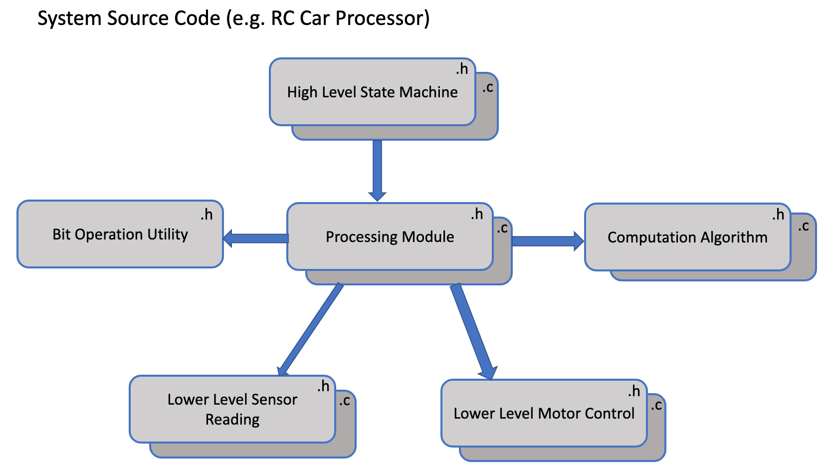
Figure 1: Example software system exhibiting dependencies between code modules.
Additionally, any non-trivial system will have many more code modules and dependencies that this single diagram. In order for us to develop the system efficiently and reliably, we need to isolate functionality as much as possible between modules. Then we can work on one part of the system without worrying about the rest of the system’s behavior. For example, in the RC car, when we modify my GPS string processing algorithm, we do not want to waste time worrying if a code change breaks the motor control code. Therefore, the main goals are functional isolation between modules and a guarantee of functional correctness for each module.
We achieve functional isolation by breaking the code up into many modules with clean interfaces. Unit tests help us do that by forcing clean interfaces which can be called from the tests, minimizing large “hidden static helpers”. Unit tests also help us achieve the guarantee of functional correctness for each code module. The more robust unit tests we have that are passing for that module, the more confident we can be that the module is behaving as required.
Mocking Dependencies for Unit Tests
Figure 2 shows this idea for the Processing Module. We need to provide a “guarantee” to the State Machine module that the Processing Module behaves as required in all the conditions we can think of. Therefore, we want to isolate the Processing Module as the “Unit Under Test” (UUT) and write unit tests for it. Similarly, we don’t want the behavior of the module to be tied to internal details of its dependencies (Sensor, Motor, algorithm modules, etc...), so we “mock” them to achieve this isolation. We can then control the behavior of the mocks so that for arbitrary input conditions from the dependencies, we can test the expected behavior of the Processing Module through the unit tests written in the Unity/CMock test suite.
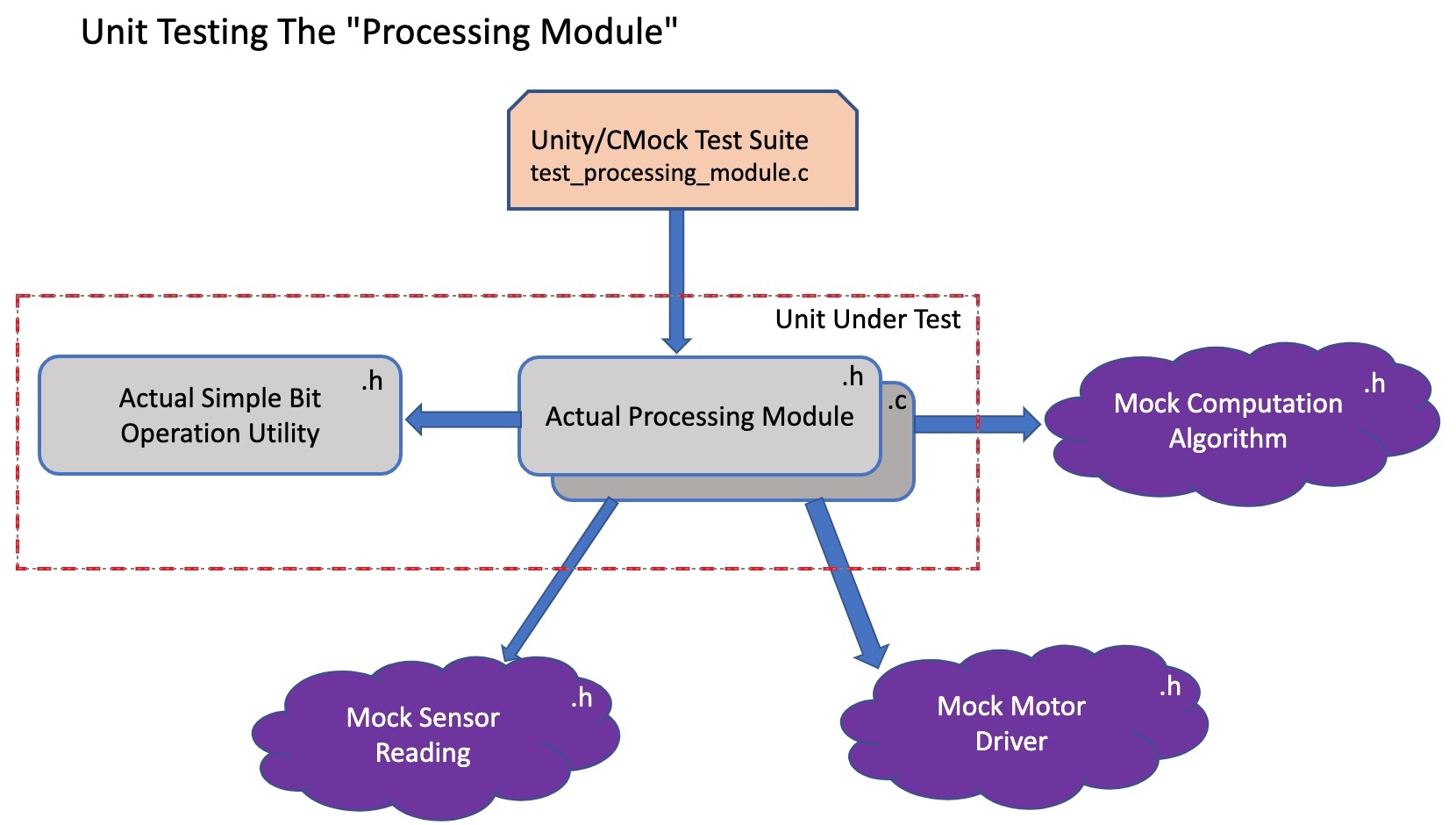
Figure 2: Visualizing the mocked dependencies of the Unit-Under-Test module.
A subtle example from class is the case where we don’t mock ALL dependencies. In this case, the Bit Operation Utility is a simple header class with no dependencies. We don’t mind to include the actual implementation so that the unit tests can also verify its correctness directly. There would not be much value in creating separate unit tests for that module because its behavior is so trivial.
Summary
We want to isolate each of our code modules to test it, and we mock all of its dependencies to achieve this isolation. The mocked dependencies then give us control over their behavior in order to achieve desired UUT behavior scenarios, similar to a “testbench” in electronics.
Navigating a Processor's Reference Manual
Overview
Even though our project mostly utilizes pre-developed drivers for ADC, GPIO, CAN, etc... peripherals for our RC car project, we still need to have a good understanding of their underlying usage. This is even more important if we need to debug any integration issues when connecting new sensors or components as we build the car. If we end up using a new peripheral for a component, we need to know how to write our own driver for it. At that point, we need to navigate our processor's reference manual to learn the peripheral's functionality and configuration.
Reference Manual vs Datasheet
LPC408x Reference Manual: Reference Manual
The Reference Manual contains all functional and usage descriptions of the processor series and its peripherals. The Datasheet describes the mechanical and electrical characteristics of the specific processor model. For our purposes, we can think of using the Reference Manual to learn about a certain peripheral (UART, CAN, etc...) and how to configure it, while using the Datasheet to figure out what external pins we can use to connect to the peripheral.
How to Find the Details of a Peripheral You Are Working With
The reference manual is a huge document, so we always need to have a specific peripheral in mind and start with the table of contents. For our example, we will use the CAN peripheral. We look for the chapter that contains the "CAN Controller". This same process works for any other peripheral like UART, PWM, etc...
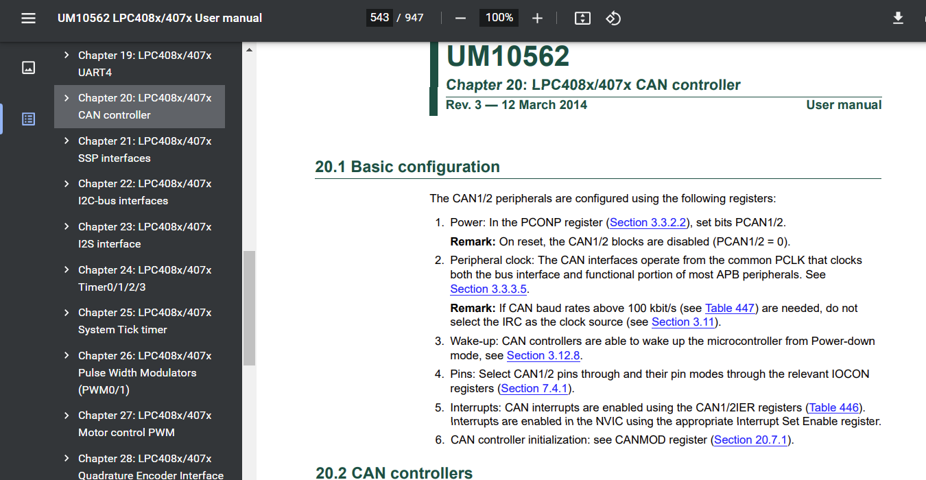
Figure 1: Using the Table of Contents to find the specific peripheral
The Peripheral chapter contains its own informal table of contents with links to each section for configuration, functional description, and register details. We should read the functional description sections to get an understanding of how the peripheral could be used and any special functionalities. After understanding the peripheral, the next step is to learn about its registers and their configuration. Each peripheral chapter has a section for "Register description" which lists all registers.
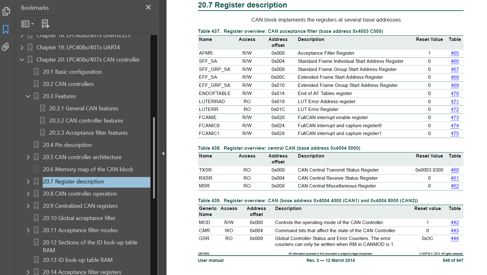
Figure 2: The Register list section of the CAN peripheral chapter
From this list, we can link directly to a specific register you need to use. There will be a description of the controls contained within that specific register.
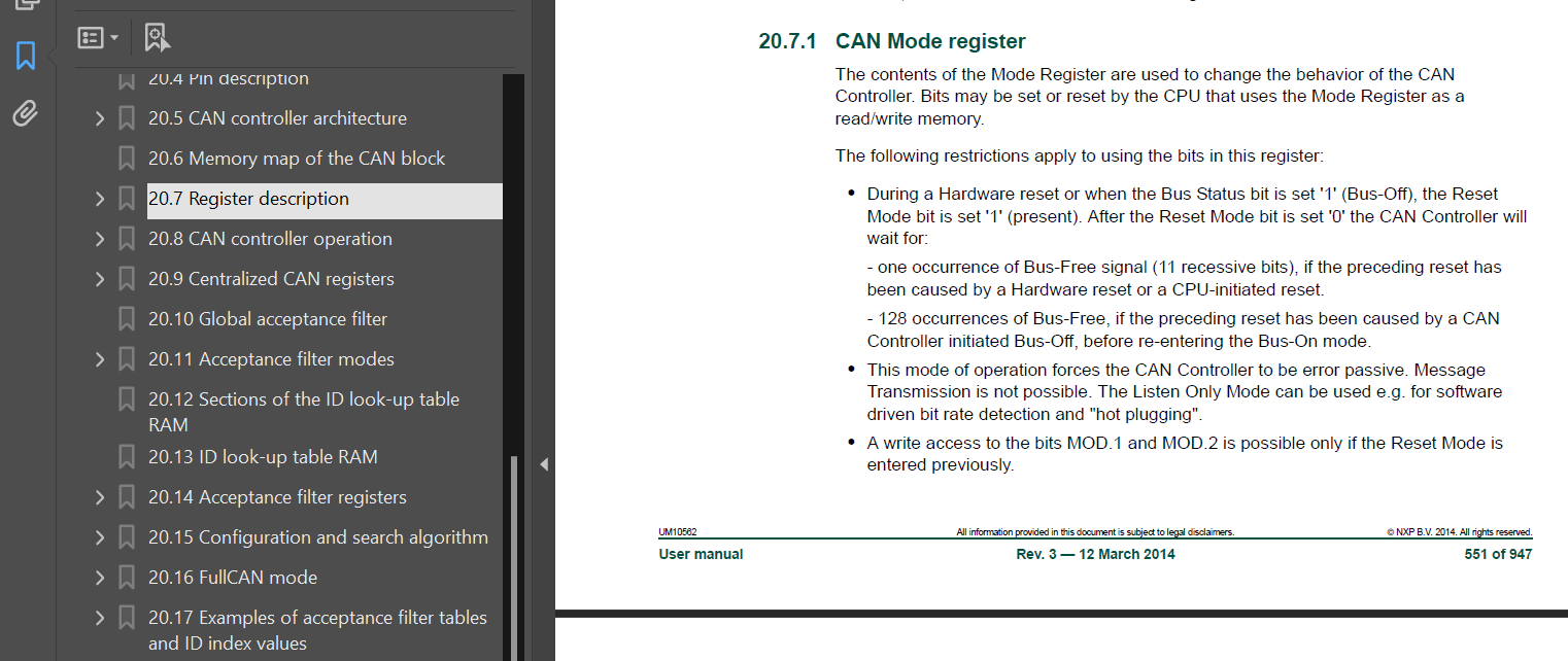
Figure 3: Description of the CAN1MOD register and any relevant considerations
After the description, we will find the list of all control bits inside that specific register, along with their usage description.
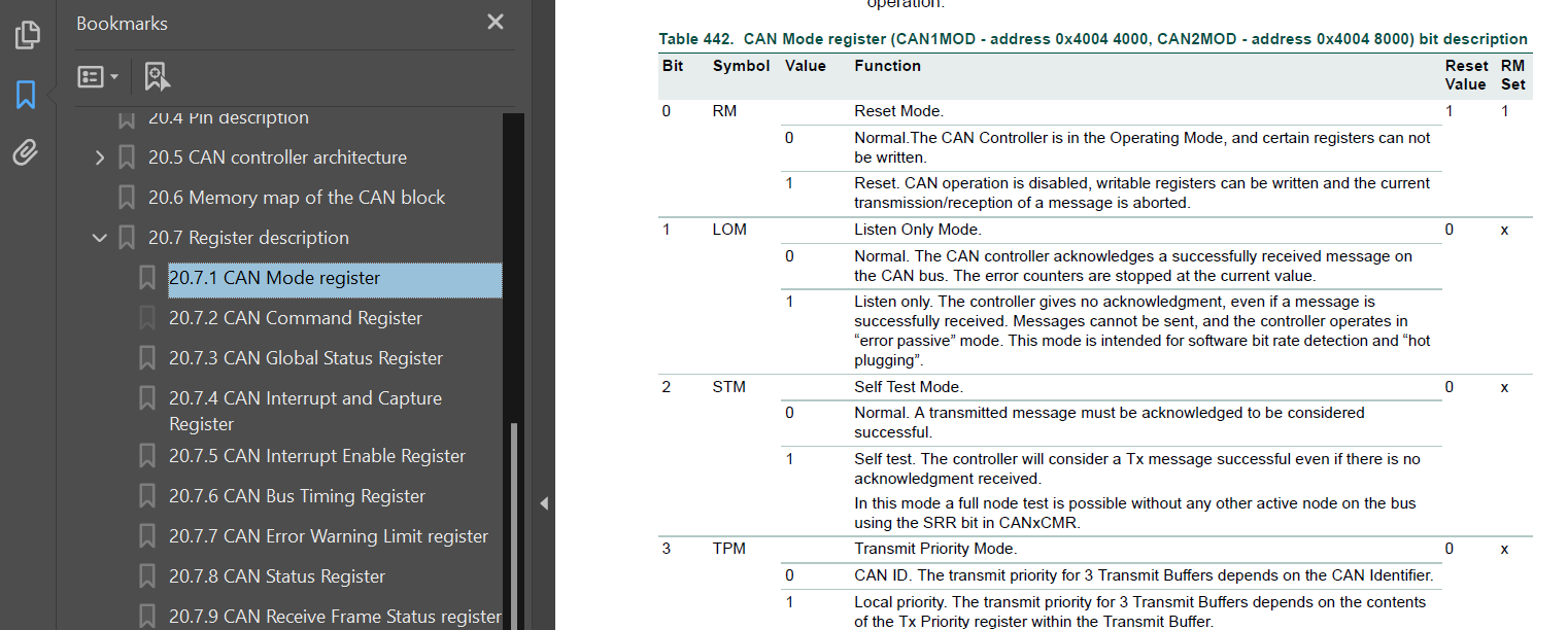
Figure 4: Control bit descriptions for the entire CAN1MOD register
Using the Datasheet to Find Pin Outputs
LPC408x Datasheet: Datasheet
The last step when using a peripheral is to determine which GPIO pins can be used to connect to an external circuit or component. The datasheet (separate document) describes each pin connection and its available usages on our specific processor model. In this example, we see that the CAN1 receiver input signal is connected to the P0[0] (labeled P0.0 on the SJTwo board) GPIO pin.
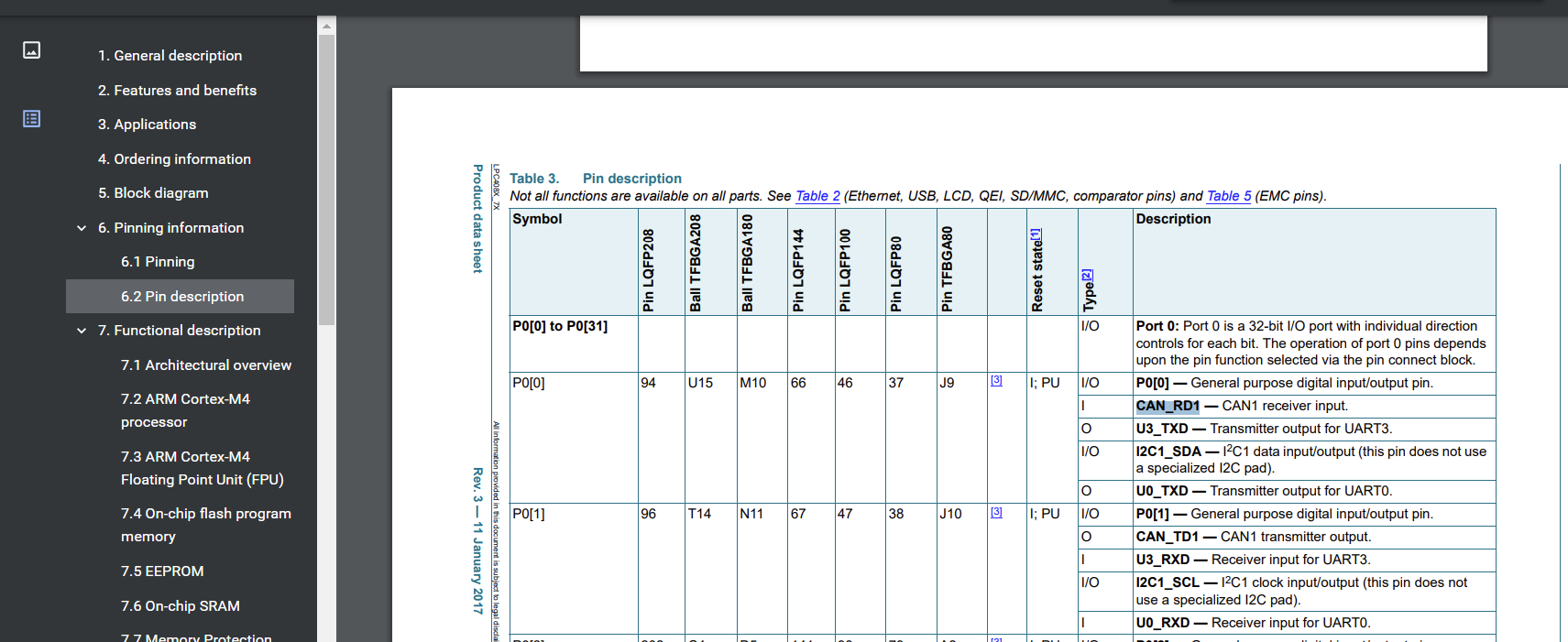
Figure 5: Processor Datasheet pin descriptions for all physical pin connections
This matches the exposed breakout pin P0.0 on our SJ-Two board for the CAN1 peripheral: