Lesson Interrupts
- Lookup Tables
- Binary Semaphores
- Nested Vector Interrupt Controller (NVIC)
- Lab: Interrupts and Binary Semaphores
Lookup Tables
Objective
To discuss lookup tables and how to use them to sacrifice storage space to increase computation time.
What Are Lookup Tables
Lookup tables are static arrays that sacrifices memory storage in place of a simple array index lookup of precalculated values. In some examples, a lookup table is not meant to speed a process, but simply an elegant solution to a problem.
Lets look at some examples to see why these are useful.
Why Use Lookup Tables
Simple Example: Convert Potentiometer Voltage to Angle
Lets make some assumptions about the system first:
- Using an 8-bit ADC
- Potentiometer is linear
- Potentiometer sweep angle is 180 or 270 degrees
- Potentiometer all the way left is 0 deg and 0V
- Potentiometer all the way right (180/270 deg) is ADC Reference Voltage
- Using a processor that does NOT have a FPU (Floating Point arithmetic Unit) like the Arm Cortex M3 we use in the LPC1756.
double potADCToDegrees(uint8_t adc)
{
	return ((double)(adc))*(270/256);
}
Code Block 1. Without Lookup
const double potentiometer_angles[256] =
{
//  [ADC] = Angle
	[0]		= 0.0,
	[1] 	= 1.0546875,
	[2] 	= 2.109375,
	[3] 	= 3.1640625,
	[4] 	= 4.21875,
	[5] 	= 5.2734375,
	[6] 	= 6.328125,
	[7] 	= 7.3828125,
	[8] 	= 8.4375,
	[9] 	= 9.4921875,
	[10] 	= 10.546875,
	[11] 	= 11.6015625,
	[12] 	= 12.65625,
	[13] 	= 13.7109375,
	[14] 	= 14.765625,
	[15] 	= 15.8203125,
	[16] 	= 16.875,
	[17] 	= 17.9296875,
	[18] 	= 18.984375,
	[19] 	= 20.0390625,
	[20] 	= 21.09375,
	[21] 	= 22.1484375,
	[22] 	= 23.203125,
	[23] 	= 24.2578125,
	[24] 	= 25.3125,
	[25] 	= 26.3671875,
	[26] 	= 27.421875,
	[27] 	= 28.4765625,
	[28] 	= 29.53125,
	[29] 	= 30.5859375,
	[30] 	= 31.640625,
	[31] 	= 32.6953125,
	[32] 	= 33.75,
	[33] 	= 34.8046875,
	[34] 	= 35.859375,
	[35] 	= 36.9140625,
	[36] 	= 37.96875,
	[37] 	= 39.0234375,
	[38] 	= 40.078125,
	[39] 	= 41.1328125,
	[40] 	= 42.1875,
	[41] 	= 43.2421875,
	[42] 	= 44.296875,
	[43] 	= 45.3515625,
	[44] 	= 46.40625,
	[45] 	= 47.4609375,
	[46] 	= 48.515625,
	[47] 	= 49.5703125,
	[48] 	= 50.625,
	[49] 	= 51.6796875,
	[50] 	= 52.734375,
	[51] 	= 53.7890625,
	[52] 	= 54.84375,
	[53] 	= 55.8984375,
	[54] 	= 56.953125,
	[55] 	= 58.0078125,
	[56] 	= 59.0625,
	[57] 	= 60.1171875,
	[58] 	= 61.171875,
	[59] 	= 62.2265625,
	[60] 	= 63.28125,
	[61] 	= 64.3359375,
	[62] 	= 65.390625,
	[63] 	= 66.4453125,
	[64] 	= 67.5,
	[65] 	= 68.5546875,
	[66] 	= 69.609375,
	[67] 	= 70.6640625,
	[68] 	= 71.71875,
	[69] 	= 72.7734375,
	[70] 	= 73.828125,
	[71] 	= 74.8828125,
	[72] 	= 75.9375,
	[73] 	= 76.9921875,
	[74] 	= 78.046875,
	[75] 	= 79.1015625,
	[76] 	= 80.15625,
	[77] 	= 81.2109375,
	[78] 	= 82.265625,
	[79] 	= 83.3203125,
	[80] 	= 84.375,
	[81] 	= 85.4296875,
	[82] 	= 86.484375,
	[83] 	= 87.5390625,
	[84] 	= 88.59375,
	[85] 	= 89.6484375,
	[86] 	= 90.703125,
	[87] 	= 91.7578125,
	[88] 	= 92.8125,
	[89] 	= 93.8671875,
	[90] 	= 94.921875,
	[91] 	= 95.9765625,
	[92] 	= 97.03125,
	[93] 	= 98.0859375,
	[94] 	= 99.140625,
	[95] 	= 100.1953125,
	[96] 	= 101.25,
	[97] 	= 102.3046875,
	[98] 	= 103.359375,
	[99] 	= 104.4140625,
	[100] 	= 105.46875,
    // ...
	[240] 	= 253.125,
	[241] 	= 254.1796875,
	[242] 	= 255.234375,
	[243] 	= 256.2890625,
	[244] 	= 257.34375,
	[245] 	= 258.3984375,
	[246] 	= 259.453125,
	[247] 	= 260.5078125,
	[248] 	= 261.5625,
	[249] 	= 262.6171875,
	[250] 	= 263.671875,
	[251] 	= 264.7265625,
	[252] 	= 265.78125,
	[253] 	= 266.8359375,
	[254] 	= 267.890625,
	[255] 	= 268.9453125,
	[256] 	= 270
};

inline double potADCToDegrees(uint8_t adc)
{
	return potentiometer_angles[adc];
}
Code Block 2. With Lookup
With the two examples, it may seem trivial since the WITHOUT case is only "really" doing one calculation, mulitplying the uint8_t with (270/256) since the compiler will most likely optimize this value to its result. But if you take a look at the assembly, the results may shock you.
Look up Table Disassembly
00016e08 <main>:
main():
/var/www/html/SJSU-Dev/firmware/Experiements/L5_Application/main.cpp:322
    [254]   = 268.9411765,
    [255]   = 270
};

int main(void)
{
   16e08:	b082      	sub	sp, #8
/var/www/html/SJSU-Dev/firmware/Experiements/L5_Application/main.cpp:323
    volatile double a = potentiometer_angles[15];
   16e0a:	a303      	add	r3, pc, #12	; (adr r3, 16e18 <main+0x10>)
   16e0c:	e9d3 2300 	ldrd	r2, r3, [r3]
   16e10:	e9cd 2300 	strd	r2, r3, [sp]
   16e14:	e7fe      	b.n	16e14 <main+0xc>
   16e16:	bf00      	nop
   16e18:	c3b9a8ae 	.word	0xc3b9a8ae
   16e1c:	402fc3c3 	.word	0x402fc3c3
Code Block 3. Dissassembly of Look up Table
Looks about right. You can see at 16e0a the software is retrieving data from the lookup table, and then it is loading it into the double which is on the stack.
Double Floating Point Disassembly
00017c64 <__adddf3>:
__aeabi_dadd():
   17c64:	b530      	push	{r4, r5, lr}
   17c66:	ea4f 0441 	mov.w	r4, r1, lsl #1
   17c6a:	ea4f 0543 	mov.w	r5, r3, lsl #1
   17c6e:	ea94 0f05 	teq	r4, r5
   17c72:	bf08      	it	eq
   17c74:	ea90 0f02 	teqeq	r0, r2
   17c78:	bf1f      	itttt	ne
   17c7a:	ea54 0c00 	orrsne.w	ip, r4, r0
   17c7e:	ea55 0c02 	orrsne.w	ip, r5, r2
   17c82:	ea7f 5c64 	mvnsne.w	ip, r4, asr #21
   17c86:	ea7f 5c65 	mvnsne.w	ip, r5, asr #21
   17c8a:	f000 80e2 	beq.w	17e52 <__adddf3+0x1ee>
   17c8e:	ea4f 5454 	mov.w	r4, r4, lsr #21
   17c92:	ebd4 5555 	rsbs	r5, r4, r5, lsr #21
   17c96:	bfb8      	it	lt
   17c98:	426d      	neglt	r5, r5
   17c9a:	dd0c      	ble.n	17cb6 <__adddf3+0x52>
   17c9c:	442c      	add	r4, r5
   17c9e:	ea80 0202 	eor.w	r2, r0, r2
   17ca2:	ea81 0303 	eor.w	r3, r1, r3
   17ca6:	ea82 0000 	eor.w	r0, r2, r0
   17caa:	ea83 0101 	eor.w	r1, r3, r1
   17cae:	ea80 0202 	eor.w	r2, r0, r2
   17cb2:	ea81 0303 	eor.w	r3, r1, r3
   17cb6:	2d36      	cmp	r5, #54	; 0x36
   17cb8:	bf88      	it	hi
   17cba:	bd30      	pophi	{r4, r5, pc}
   17cbc:	f011 4f00 	tst.w	r1, #2147483648	; 0x80000000
   17cc0:	ea4f 3101 	mov.w	r1, r1, lsl #12
   17cc4:	f44f 1c80 	mov.w	ip, #1048576	; 0x100000
   17cc8:	ea4c 3111 	orr.w	r1, ip, r1, lsr #12
   17ccc:	d002      	beq.n	17cd4 <__adddf3+0x70>
   17cce:	4240      	negs	r0, r0
   17cd0:	eb61 0141 	sbc.w	r1, r1, r1, lsl #1
   17cd4:	f013 4f00 	tst.w	r3, #2147483648	; 0x80000000
   17cd8:	ea4f 3303 	mov.w	r3, r3, lsl #12
   17cdc:	ea4c 3313 	orr.w	r3, ip, r3, lsr #12
   17ce0:	d002      	beq.n	17ce8 <__adddf3+0x84>
   17ce2:	4252      	negs	r2, r2
   17ce4:	eb63 0343 	sbc.w	r3, r3, r3, lsl #1
   17ce8:	ea94 0f05 	teq	r4, r5
   17cec:	f000 80a7 	beq.w	17e3e <__adddf3+0x1da>
   17cf0:	f1a4 0401 	sub.w	r4, r4, #1
   17cf4:	f1d5 0e20 	rsbs	lr, r5, #32
   17cf8:	db0d      	blt.n	17d16 <__adddf3+0xb2>
   17cfa:	fa02 fc0e 	lsl.w	ip, r2, lr
   17cfe:	fa22 f205 	lsr.w	r2, r2, r5
   17d02:	1880      	adds	r0, r0, r2
   17d04:	f141 0100 	adc.w	r1, r1, #0
   17d08:	fa03 f20e 	lsl.w	r2, r3, lr
   17d0c:	1880      	adds	r0, r0, r2
   17d0e:	fa43 f305 	asr.w	r3, r3, r5
   17d12:	4159      	adcs	r1, r3
   17d14:	e00e      	b.n	17d34 <__adddf3+0xd0>
   17d16:	f1a5 0520 	sub.w	r5, r5, #32
   17d1a:	f10e 0e20 	add.w	lr, lr, #32
   17d1e:	2a01      	cmp	r2, #1
   17d20:	fa03 fc0e 	lsl.w	ip, r3, lr
   17d24:	bf28      	it	cs
   17d26:	f04c 0c02 	orrcs.w	ip, ip, #2
   17d2a:	fa43 f305 	asr.w	r3, r3, r5
   17d2e:	18c0      	adds	r0, r0, r3
   17d30:	eb51 71e3 	adcs.w	r1, r1, r3, asr #31
   17d34:	f001 4500 	and.w	r5, r1, #2147483648	; 0x80000000
   17d38:	d507      	bpl.n	17d4a <__adddf3+0xe6>
   17d3a:	f04f 0e00 	mov.w	lr, #0
   17d3e:	f1dc 0c00 	rsbs	ip, ip, #0
   17d42:	eb7e 0000 	sbcs.w	r0, lr, r0
   17d46:	eb6e 0101 	sbc.w	r1, lr, r1
   17d4a:	f5b1 1f80 	cmp.w	r1, #1048576	; 0x100000
   17d4e:	d31b      	bcc.n	17d88 <__adddf3+0x124>
   17d50:	f5b1 1f00 	cmp.w	r1, #2097152	; 0x200000
   17d54:	d30c      	bcc.n	17d70 <__adddf3+0x10c>
   17d56:	0849      	lsrs	r1, r1, #1
   17d58:	ea5f 0030 	movs.w	r0, r0, rrx
   17d5c:	ea4f 0c3c 	mov.w	ip, ip, rrx
   17d60:	f104 0401 	add.w	r4, r4, #1
   17d64:	ea4f 5244 	mov.w	r2, r4, lsl #21
   17d68:	f512 0f80 	cmn.w	r2, #4194304	; 0x400000
   17d6c:	f080 809a 	bcs.w	17ea4 <__adddf3+0x240>
   17d70:	f1bc 4f00 	cmp.w	ip, #2147483648	; 0x80000000
   17d74:	bf08      	it	eq
   17d76:	ea5f 0c50 	movseq.w	ip, r0, lsr #1
   17d7a:	f150 0000 	adcs.w	r0, r0, #0
   17d7e:	eb41 5104 	adc.w	r1, r1, r4, lsl #20
   17d82:	ea41 0105 	orr.w	r1, r1, r5
   17d86:	bd30      	pop	{r4, r5, pc}
   17d88:	ea5f 0c4c 	movs.w	ip, ip, lsl #1
   17d8c:	4140      	adcs	r0, r0
   17d8e:	eb41 0101 	adc.w	r1, r1, r1
   17d92:	f411 1f80 	tst.w	r1, #1048576	; 0x100000
   17d96:	f1a4 0401 	sub.w	r4, r4, #1
   17d9a:	d1e9      	bne.n	17d70 <__adddf3+0x10c>
   17d9c:	f091 0f00 	teq	r1, #0
   17da0:	bf04      	itt	eq
   17da2:	4601      	moveq	r1, r0
   17da4:	2000      	moveq	r0, #0
   17da6:	fab1 f381 	clz	r3, r1
   17daa:	bf08      	it	eq
   17dac:	3320      	addeq	r3, #32
   17dae:	f1a3 030b 	sub.w	r3, r3, #11
   17db2:	f1b3 0220 	subs.w	r2, r3, #32
   17db6:	da0c      	bge.n	17dd2 <__adddf3+0x16e>
   17db8:	320c      	adds	r2, #12
   17dba:	dd08      	ble.n	17dce <__adddf3+0x16a>
   17dbc:	f102 0c14 	add.w	ip, r2, #20
   17dc0:	f1c2 020c 	rsb	r2, r2, #12
   17dc4:	fa01 f00c 	lsl.w	r0, r1, ip
   17dc8:	fa21 f102 	lsr.w	r1, r1, r2
   17dcc:	e00c      	b.n	17de8 <__adddf3+0x184>
   17dce:	f102 0214 	add.w	r2, r2, #20
   17dd2:	bfd8      	it	le
   17dd4:	f1c2 0c20 	rsble	ip, r2, #32
   17dd8:	fa01 f102 	lsl.w	r1, r1, r2
   17ddc:	fa20 fc0c 	lsr.w	ip, r0, ip
   17de0:	bfdc      	itt	le
   17de2:	ea41 010c 	orrle.w	r1, r1, ip
   17de6:	4090      	lslle	r0, r2
   17de8:	1ae4      	subs	r4, r4, r3
   17dea:	bfa2      	ittt	ge
   17dec:	eb01 5104 	addge.w	r1, r1, r4, lsl #20
   17df0:	4329      	orrge	r1, r5
   17df2:	bd30      	popge	{r4, r5, pc}
   17df4:	ea6f 0404 	mvn.w	r4, r4
   17df8:	3c1f      	subs	r4, #31
   17dfa:	da1c      	bge.n	17e36 <__adddf3+0x1d2>
   17dfc:	340c      	adds	r4, #12
   17dfe:	dc0e      	bgt.n	17e1e <__adddf3+0x1ba>
   17e00:	f104 0414 	add.w	r4, r4, #20
   17e04:	f1c4 0220 	rsb	r2, r4, #32
   17e08:	fa20 f004 	lsr.w	r0, r0, r4
   17e0c:	fa01 f302 	lsl.w	r3, r1, r2
   17e10:	ea40 0003 	orr.w	r0, r0, r3
   17e14:	fa21 f304 	lsr.w	r3, r1, r4
   17e18:	ea45 0103 	orr.w	r1, r5, r3
   17e1c:	bd30      	pop	{r4, r5, pc}
   17e1e:	f1c4 040c 	rsb	r4, r4, #12
   17e22:	f1c4 0220 	rsb	r2, r4, #32
   17e26:	fa20 f002 	lsr.w	r0, r0, r2
   17e2a:	fa01 f304 	lsl.w	r3, r1, r4
   17e2e:	ea40 0003 	orr.w	r0, r0, r3
   17e32:	4629      	mov	r1, r5
   17e34:	bd30      	pop	{r4, r5, pc}
   17e36:	fa21 f004 	lsr.w	r0, r1, r4
   17e3a:	4629      	mov	r1, r5
   17e3c:	bd30      	pop	{r4, r5, pc}
   17e3e:	f094 0f00 	teq	r4, #0
   17e42:	f483 1380 	eor.w	r3, r3, #1048576	; 0x100000
   17e46:	bf06      	itte	eq
   17e48:	f481 1180 	eoreq.w	r1, r1, #1048576	; 0x100000
   17e4c:	3401      	addeq	r4, #1
   17e4e:	3d01      	subne	r5, #1
   17e50:	e74e      	b.n	17cf0 <__adddf3+0x8c>
   17e52:	ea7f 5c64 	mvns.w	ip, r4, asr #21
   17e56:	bf18      	it	ne
   17e58:	ea7f 5c65 	mvnsne.w	ip, r5, asr #21
   17e5c:	d029      	beq.n	17eb2 <__adddf3+0x24e>
   17e5e:	ea94 0f05 	teq	r4, r5
   17e62:	bf08      	it	eq
   17e64:	ea90 0f02 	teqeq	r0, r2
   17e68:	d005      	beq.n	17e76 <__adddf3+0x212>
   17e6a:	ea54 0c00 	orrs.w	ip, r4, r0
   17e6e:	bf04      	itt	eq
   17e70:	4619      	moveq	r1, r3
   17e72:	4610      	moveq	r0, r2
   17e74:	bd30      	pop	{r4, r5, pc}
   17e76:	ea91 0f03 	teq	r1, r3
   17e7a:	bf1e      	ittt	ne
   17e7c:	2100      	movne	r1, #0
   17e7e:	2000      	movne	r0, #0
   17e80:	bd30      	popne	{r4, r5, pc}
   17e82:	ea5f 5c54 	movs.w	ip, r4, lsr #21
   17e86:	d105      	bne.n	17e94 <__adddf3+0x230>
   17e88:	0040      	lsls	r0, r0, #1
   17e8a:	4149      	adcs	r1, r1
   17e8c:	bf28      	it	cs
   17e8e:	f041 4100 	orrcs.w	r1, r1, #2147483648	; 0x80000000
   17e92:	bd30      	pop	{r4, r5, pc}
   17e94:	f514 0480 	adds.w	r4, r4, #4194304	; 0x400000
   17e98:	bf3c      	itt	cc
   17e9a:	f501 1180 	addcc.w	r1, r1, #1048576	; 0x100000
   17e9e:	bd30      	popcc	{r4, r5, pc}
   17ea0:	f001 4500 	and.w	r5, r1, #2147483648	; 0x80000000
   17ea4:	f045 41fe 	orr.w	r1, r5, #2130706432	; 0x7f000000
   17ea8:	f441 0170 	orr.w	r1, r1, #15728640	; 0xf00000
   17eac:	f04f 0000 	mov.w	r0, #0
   17eb0:	bd30      	pop	{r4, r5, pc}
   17eb2:	ea7f 5c64 	mvns.w	ip, r4, asr #21
   17eb6:	bf1a      	itte	ne
   17eb8:	4619      	movne	r1, r3
   17eba:	4610      	movne	r0, r2
   17ebc:	ea7f 5c65 	mvnseq.w	ip, r5, asr #21
   17ec0:	bf1c      	itt	ne
   17ec2:	460b      	movne	r3, r1
   17ec4:	4602      	movne	r2, r0
   17ec6:	ea50 3401 	orrs.w	r4, r0, r1, lsl #12
   17eca:	bf06      	itte	eq
   17ecc:	ea52 3503 	orrseq.w	r5, r2, r3, lsl #12
   17ed0:	ea91 0f03 	teqeq	r1, r3
   17ed4:	f441 2100 	orrne.w	r1, r1, #524288	; 0x80000
   17ed8:	bd30      	pop	{r4, r5, pc}
   17eda:	bf00      	nop
Code Block 4. Arm Software Floating Point Addition Implementation
This isn't even the full code. This is a function that our calculation function has to run each time it wants to add two doubles together. Also, note that it is not just a straight shot of 202 instructions, because you can see that there are loops in the code where ever you see an instruction's mnemonic that starts with the letter b (stands for branch).
Other Use Cases
- Correlate degrees to radians (assuming degrees are whole numbers)
- Table of cosine or sine given radians or degrees
- In the radians case, you will need to create your own trivial hashing function to convert radians to an index
- Finding a number of bits SET in a 32-bit number
- Without a lookup table time complexity is O(n) where (n = 32), the number of bits you want to look through
- With a lookup table, the time complexity is O(1), constant time, and only needs the followin operations
- 3 bitwise left shifts operations
- 4 bitwise ANDS operations
- 4 load from memory addresses
- 4 binary ADD operations
- Total of 15 operations total
/* Found this on wikipedia! */

/* Pseudocode of the lookup table 'uint32_t bits_set[256]' */
 /*                    0b00, 0b01, 0b10, 0b11, 0b100, 0b101, ... */
 int bits_set[256] = {    0,    1,    1,    2,     1,     2, // 200+ more entries

 /* (this code assumes that 'int' is an unsigned 32-bits wide integer) */
 int count_ones(unsigned int x) {
    return bits_set[ x        & 255] + bits_set[(x >>  8) & 255]
         + bits_set[(x >> 16) & 255] + bits_set[(x >> 24) & 255];
 }
Code Block 5. Bits set in a 32-bit number (Found this on wikipedia (look up tables))
There are far more use cases then this, but these are a few.
Lookup Table Decision Tree
Lookup tables can be used as elegant ways to structure information. In this case, they may not provide a speed up but they will associate indexes with something greater, making your code more readable and easier to maintain. In this example, we will be looking at a matrix of function pointers.
Example: Replace Decision Tree
See the function below:
void makeADecisionRobot(bool power_system_nominal, bool no_obstacles_ahead)
{
   if(power_system_nominal && no_obstacles_ahead) {
      moveForward();
   }
   else if(power_system_nominal && !no_obstacles_ahead) {
      moveOutOfTheWay();
   }
   else if(!power_system_nominal && no_obstacles_ahead) {
      slowDown();
   }
   else {
      emergencyStop();
   }
}
Code Block 6. Typical Decision Tree
void (* decision_matrix[2][2])(void) =
{
   [1][1] = moveForward,
   [1][0] = moveOutOfTheWay,
   [0][1] = slowDown,
   [0][0] = emergencyStop,
};

void makeADecisionRobot(bool power_system_nominal, bool no_obstacles_ahead)
{
   decision_matrix[power_system_nominal][no_obstacles_ahead]();
}
Code Block 7. Lookup Table Decision Tree
The interesting thing about the decision tree is that it is also more optimal in that, it takes a few instructions to do the look up from memory, then the address of the procedure [function] is looked up an executed, where the former required multiple read instructions and comparison instructions.
This pattern of lookup table will be most useful to us for the interrupts lab assignment.
Binary Semaphores
Semaphores are used to signal/synchronize tasks as well as protect resources.
A binary semaphore can (and should) be used as a means of signaling a task. This signal can come from an interrupt service routine or from another task. A semaphore is an RTOS primitive and is guaranteed to be thread-safe.
Design Pattern
Wake Up On Semaphore
The idea here is to have a task that is waiting on a semaphore and when it is given by an ISR or an other task, this task unblocks, and runs its code. This results in a task that usually sleeping/blocked and not utilizing CPU time unless its been called upon. In FreeRTOS, there is a similar facility provided which is called 'deferred interrupt processing'. This could be used to signal an emergency shutdown procedure when a button is triggered, or to trigger a procedure when the state of the system reaches a fault condition. Sample code below:
/* Declare the instance of the semaphore but not that you have to still 'create' it which is done in the main() */
SemaphoreHandle_t xSemaphore;

void wait_on_semaphore_task(void * pvParameters) {
    while(1) {
        /* Wait forever until a the semaphore is sent/given */
        if(xSemaphoreTake(xSemaphore, portMAX_DELAY)) {
            printf("Semaphore taken\n");
            /* Do more stuff below ... */
        }
    }
}

void semaphore_supplier_task(void * pvParameters) {
    while(1) {
        if(checkButtonStatus()) {
            xSemaphoreGive(xSemaphore);
        }
        /* Do more stuff ... */
    }
}

int main()
{
    /* Semaphore starts 'empty' when you create it */
    xSemaphore = xSemaphoreCreateBinary();

    /* Create the tasks */
    const uint32_t STACK_SIZE_WORDS = 128;
    xTaskCreate(wait_on_semaphore_task, "Waiter", 512, NULL, PRIORITY_LOW, NULL);
    xTaskCreate(semaphore_supplier_task, "Supplier", 512, NULL, PRIORITY_LOW, NULL);

    /* Start Scheduler */
    vTaskStartScheduler();
}
Code Block 1. How to use Semaphores and use as a wake up pattern
Semaphore as a flag
The idea of this is to have a code loop that checks the semaphore periodically with the 'block time' of your choice. The task will only react when it notices that the semaphore flag has been given. When your task takes it, it will run an if statement block and continue its loop. Keep in mind this will consume your flag, so the consumer will loop back and check for the presence of the new flag in the following loop.
void vWaitOnSemaphore( void * pvParameters )
{
    while(1) {
        /* Check the semaphore if it was set */
        if(xSemaphoreTake(xSemaphore, 0)) {
            printf("Got the Semaphore, consumed the flag indicator.");
            /* Do stuff upon taking the semaphore successfully ... */
        }

        /* Do more stuff ... */
    }
}
Code Block 2. Semaphores as a consumable flag
Interrupt Signal from ISR
This is useful, because ISRs should be as short as possible as they interrupt the software or your RTOS tasks. In this case, the ISR can defer the work to a task, which means that the ISR runtime is short. This is important because when you enter an interrupt function, the interrupts are disabled during the ISRs execution. The priority of the task can be configured based on the importance of the task reacting to the semaphore.
You may not want to defer interrupt processing if the ISR is so critical that the time it takes to allow RTOS to run is too much. For example, a power failure interrupt.
void systemInterrupt() {
    xSemaphoreGiveFromISR(xSemaphore);
}

void vSystemInterruptTask(void * pvParameter) {
    while(1) {
        if(xSemaphoreTake(xSemaphore, portMAX_DELAY)) {
            // Process the interrupt
        }
    }
}
Code Block 3. Semaphore used within an ISR
NOTICE: The FromISR after the xSemaphoreGive API call? If you are making an RTOS API call from an ISR, you must use the FromISR variant of the API call. Undefined behavior otherwise like freezing the system.
Nested Vector Interrupt Controller (NVIC)
Objective
This tutorial demonstrates how to use interrupts on a processor. In general, you will understand the concept behind interrupts on any processor, but we will use the SJ2 board as an example.
What is an interrupt?
An interrupt is the hardware capability of a CPU to break the normal flow of software to attend an urgent request.
The science behind interrupts lies in the hardware that allows the CPU to be interrupted. Each peripheral in a micro-controller may be able to assert an interrupt to the CPU core, and then the CPU core would jump to the corresponding interrupt service routine (ISR) to service the interrupt.
void main_loop(void) {
  while (forever) {
    logic();
    another_function();
    // ...
  }
}

// Interrupt on button-press
void button_press_interrupt(void) {
}
ISR Procedure
The following steps demonstrate what happens when an interrupt occurs :
- CPU manipulates the PC (program counter) to jump to the ISR
- IMPORTANT: CPU will disable interrupts (or that priority level's interrupts until the end of ISR)
- Registers are saved before running the ISR (pushed onto the stack)
- ISR is run
- Registers are restored (popped from stack)
- Interrupts are re-enabled (or that priority level's interrupt is re-enabled)
On some processors, the savings and restoring of registers is a manual step and the compiler would help you do it. You can google the "GCC interrupt attribute" to study this topic further. On the SJ2 board, which uses LPC40xx (ARM Cortex M4), this step is automatically taken care of by the CPU hardware.

Figure 1. Nested Interrupt Processing
Nested Vector Interrupt Controller
Nested Vector Interrupt Controllers or NVIC for short, have two properties:
- Can handle multiple interrupts.
- The number of interrupts implemented is device-dependent.
- A programmable priority level for each interrupt.
- A higher level corresponds to a lower priority, so level 0 is the highest interrupt priority.
- Level and pulse detection of interrupt signals.
- Grouping of priority values into group priority and sub-priority fields.
- This means that interrupts of the same priority are grouped together and do not preempt each other.
- Each interrupt also has a sub-priority field which is used to figure out the run order of pending interrupts of the same priority.
- Interrupt tail-chaining.
- This enables back-to-back interrupt processing without the overhead of state saving and restoration between interrupts.
- This saves us from the step of having to restore and then save the registers again.
- An external Non-maskable interrupt (NMI)
NVIC Interrupt Example

Figure 2. Multiple Interrupt Processing
The SW to HW Connection
Now that we understand how the CPU hardware services interrupts, we need to define how we inform the CPU WHERE our ISR function is located at.
Interrupt Vector Table
This table is nothing but addresses of functions that correspond to the microcontroller interrupts. Specific interrupts use specific "slots" in this table, and we have to populate these spots with our software functions that service the interrupts.

SJTwo (LPC40xx) Example
Using a linker script and compiler directives (commands for the compiler), the compiler is able to place the software interrupt vector table at a specific location that the CPU expects the interrupt vector table to be located at. This connects the dots about how the CPU is able to determine WHERE your interrupt service routines are located at. From there on, anytime a specific interrupt occurs, the CPU is able to fetch the address and make the JUMP.
static void halt(void);

typedef void (*void_func_ptr_t)(void);

__attribute__((section(".interrupt_vector_table"))) void_func_ptr_t interrupt_vector_table[] = {
    /**
     * Core interrupt vectors - Mandated by Cortex-M4 core
     */
    (void_func_ptr_t)&_estack, // 0 ARM: Initial stack pointer
    cpu_startup_entry_point,   // 1 ARM: Initial program counter
    halt,                      // 2 ARM: Non-maskable interrupt
    halt,                      // 3 ARM: Hard fault
    halt,                      // 4 ARM: Memory management fault
    halt,                      // 5 ARM: Bus fault
    halt,                      // 6 ARM: Usage fault
    halt,                      // 7 ARM: Reserved
    halt,                      // 8 ARM: Reserved
    halt,                      // 9 ARM: Reserved
    halt,                      // 10 ARM: Reserved
    vPortSVCHandler,           // 11 ARM: Supervisor call (SVCall)
    halt,                      // 12 ARM: Debug monitor
    halt,                      // 13 ARM: Reserved
    xPortPendSVHandler,        // 14 ARM: Pendable request for system service (PendableSrvReq)
    xPortSysTickHandler,       // 15 ARM: System Tick Timer (SysTick)

    /**
     * Device interrupt vectors - routed to a 'dispatcher' that allows users to register their ISR at this vector
     * You can 'hijack' this vector and directly install your interrupt service routine
     */
    lpc_peripheral__interrupt_dispatcher, // 16 WDT
    lpc_peripheral__interrupt_dispatcher, // 17 Timer 0
    lpc_peripheral__interrupt_dispatcher, // 18 Timer 1
    lpc_peripheral__interrupt_dispatcher, // 19 Timer 2
    lpc_peripheral__interrupt_dispatcher, // 20 Timer 3
    lpc_peripheral__interrupt_dispatcher, // 21 UART 0
    lpc_peripheral__interrupt_dispatcher, // 22 UART 1
    lpc_peripheral__interrupt_dispatcher, // 23 UART 2
    lpc_peripheral__interrupt_dispatcher, // 24 UART 3
    lpc_peripheral__interrupt_dispatcher, // 25 PWM 1
    lpc_peripheral__interrupt_dispatcher, // 26 I2C 0
    lpc_peripheral__interrupt_dispatcher, // 27 I2C 1
    lpc_peripheral__interrupt_dispatcher, // 28 I2C 2
    lpc_peripheral__interrupt_dispatcher, // 29 UNUSED
    lpc_peripheral__interrupt_dispatcher, // 30 SSP 0
    lpc_peripheral__interrupt_dispatcher, // 31 SSP 1
    lpc_peripheral__interrupt_dispatcher, // 32 PLL 0
    lpc_peripheral__interrupt_dispatcher, // 33 RTC and Event Monitor/Recorder
    lpc_peripheral__interrupt_dispatcher, // 34 External Interrupt 0 (EINT 0)
    lpc_peripheral__interrupt_dispatcher, // 35 External Interrupt 1 (EINT 1)
    lpc_peripheral__interrupt_dispatcher, // 36 External Interrupt 2 (EINT 2)
    lpc_peripheral__interrupt_dispatcher, // 37 External Interrupt 3 (EINT 3)
    lpc_peripheral__interrupt_dispatcher, // 38 ADC
    lpc_peripheral__interrupt_dispatcher, // 39 BOD
    lpc_peripheral__interrupt_dispatcher, // 40 USB
    lpc_peripheral__interrupt_dispatcher, // 41 CAN
    lpc_peripheral__interrupt_dispatcher, // 42 DMA Controller
    lpc_peripheral__interrupt_dispatcher, // 43 I2S
    lpc_peripheral__interrupt_dispatcher, // 44 Ethernet
    lpc_peripheral__interrupt_dispatcher, // 45 SD Card Interface
    lpc_peripheral__interrupt_dispatcher, // 46 Motor Control PWM
    lpc_peripheral__interrupt_dispatcher, // 47 PLL 1
    lpc_peripheral__interrupt_dispatcher, // 48 Quadrature Encoder
    lpc_peripheral__interrupt_dispatcher, // 49 USB Activity
    lpc_peripheral__interrupt_dispatcher, // 50 CAN Activity
    lpc_peripheral__interrupt_dispatcher, // 51 UART 4
    lpc_peripheral__interrupt_dispatcher, // 52 SSP 2
    lpc_peripheral__interrupt_dispatcher, // 53 LCD
    lpc_peripheral__interrupt_dispatcher, // 54 GPIO Interrupt
    lpc_peripheral__interrupt_dispatcher, // 55 PWM 0
    lpc_peripheral__interrupt_dispatcher, // 56 EEPROM
};

static void halt(void) {
  // This statement resolves compiler warning: variable define but not used
  (void)interrupt_vector_table;

  while (true) {
  }
}
Code Block 1. Software Interrupt Vector Table
NOTE: that a vector table is really just a lookup table that hardware utilizes.
Two Methods to set up an ISR on the SJ2
All of the methods require that you run this function to allow the NVIC to accept a particular interrupt request.
NVIC_EnableIRQ(EINT3_IRQn);
Where the input is the IRQ number. This can be found in the LCP40xx.h file. Search for enum IRQn.
Method 1. Modify IVT
We discourage modifying the interrupt_vector_table.c (or startup.cpp for SJ2) vector tables directly.
IVT modify
__attribute__((section(".interrupt_vector_table"))) void_func_ptr_t interrupt_vector_table[] = {
    /**
     * Core interrupt vectors
     */
    (void_func_ptr_t)&_estack, // 0 ARM: Initial stack pointer
    cpu_startup_entry_point,   // 1 ARM: Initial program counter
    halt,                      // 2 ARM: Non-maskable interrupt
    halt,                      // 3 ARM: Hard fault
    halt,                      // 4 ARM: Memory management fault
    halt,                      // 5 ARM: Bus fault
    halt,                      // 6 ARM: Usage fault
    halt,                      // 7 ARM: Reserved
    halt,                      // 8 ARM: Reserved
    halt,                      // 9 ARM: Reserved
    halt,                      // 10 ARM: Reserved
    vPortSVCHandler,           // 11 ARM: Supervisor call (SVCall)
    halt,                      // 12 ARM: Debug monitor
    halt,                      // 13 ARM: Reserved
    xPortPendSVHandler,        // 14 ARM: Pendable request for system service (PendableSrvReq)
    xPortSysTickHandler,       // 15 ARM: System Tick Timer (SysTick)

    /**
     * Device interrupt vectors
     */
    lpc_peripheral__interrupt_dispatcher, // 16 WDT
    lpc_peripheral__interrupt_dispatcher, // 17 Timer 0
    lpc_peripheral__interrupt_dispatcher, // 18 Timer 1
    lpc_peripheral__interrupt_dispatcher, // 19 Timer 2
    lpc_peripheral__interrupt_dispatcher, // 20 Timer 3
    lpc_peripheral__interrupt_dispatcher, // 21 UART 0
    lpc_peripheral__interrupt_dispatcher, // 22 UART 1
    lpc_peripheral__interrupt_dispatcher, // 23 UART 2
    my_own_uart3_interrupt, // 24 UART 3  <-------------------- Install your function to the ISR vector directly
    // ...
};
Code Block 3. Weak Function Override Template
Method 2. ISR Register Function
There is a simple API defined at lpc_peripherals.h that you can use. Be sure to check the implementation of this code module to actually understand what it is doing.
This is the best option! Please use this option almost always!
// Just your run-of-the-mill function
void my_uart3_isr(void) {
    do_something();
    clear_uart3_interrupt();
}

#include "lpc_peripherals.h"
int main() {
    lpc_peripheral__enable_interrupt(LPC_PERIPHERAL__UART3, my_uart3_isr);

    // ... rest of the code
}
Code Block 5. Weak Function Override Template
| PROS | CONS |
|
|
What to do inside an ISR
Do very little inside an ISR. When you are inside an ISR, the whole system is blocked (other than higher priority interrupts). If you spend too much time inside the ISR, then you are destroying the real-time operating system principle and everything gets clogged.
With that said, here is the general guideline:
Short as possible
DO NOT POLL FOR ANYTHING! Try to keep loops as small as possible. Note that printing data over UART can freeze the entire system, including the RTOS for that duration. For instance, printing 4 chars may take 1ms at 38400bps.
FreeRTOS API calls
If you are using FreeRTOS API, you must use FromISR functions only! If a FromISR function does not exist, then don't use that API.
Clear Interrupt Sources
Clear the source of the interrupt. For example, if interrupt was for rising edge of a pin, clear the "rising edge" bit such that you will not re-enter into the same interrupt function.
If you don't do this, your interrupt will get stuck in an infinite ISR call loop. For the Port interrupts, this can be done by writing to the IntClr registers.
ISR processing inside a FreeRTOS Task
It is a popular scheme to have an ISR quickly exit, and then resume a task or thread to process the event. For example, if we wanted to write a file upon a button press, we don't want to do that inside an ISR because it would take too long and block the system. What we can utilize a wait on semaphore design pattern.
What you may argue with the example below is that we do not process the ISR immediately, and therefore delay the processing. But you can tackle this scenario by resuming a HIGHEST priority task. Immediately, after the ISR exits, due to the ISR "yield", FreeRTOS will resume the high priority task immediately rather than servicing another task
/* Create the semaphore in main() */
SemaphoreHandle_t button_press_semaphore = NULL;

void my_button_press_isr(void) {
    long yield = 0;
    xSemaphoreGiveFromISR(button_press_semaphore, &yield);
    portYIELD_FROM_ISR(yield);
}

void button_task(void *pvParameter)
{
    while(1) {
        if (xSemaphoreTake(button_press_semaphore, portMAX_DELAY)) {
            /* Process the interrupt */
        }
    }
}

void main(void)
{
    button_press_semaphore = xSemaphoreCreateBinary();
    /* TODO: Hook up my_button_press_isr() as an interrupt */
    /* TODO: Create button_task() and start FreeRTOS scheduler */
}
Code Block 6. Wait on Semaphore ISR design pattern example
Resources
http://infocenter.arm.com/help/index.jsp?topic=/com.arm.doc.ddi0489b/CACDDJHB.html
Lab: Interrupts and Binary Semaphores
Objective
Learn how to create a single dynamic user defined interrupt service routine callback driver/library. Be sure to click through the hyperlinks provided in this article to learn the background knowledge before you jump into the assignment. You may re-use any existing code, such as the API from gpio.h header file.
This lab will utilize:
- Semaphores
- Wait on Semaphore Design pattern
-
Lookup table structures and Function Pointers
- You will allow the user to register their callbacks
- Be sure to understand how function pointers work
-
Interrupts
- LPC supports rising and falling edge interrupts on certain port pins
- These port/pin interrupts are actually OR'd together and use a single CPU interrupt.
- On the SJ2 board, GPIO interrupts are handled by a dedicated GPIO interrupt (exception number 54)
- For the SJ1 board, it is: EINT3 interrupt.
Where to start
-
For Part 0, do the following
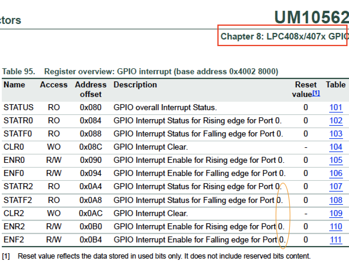
- Read the LPC User Manual, particularly ALL information about
Table 95: GPIO Interrupt - Browse the code, and fully absorb
interrupt_vector_table.candentry_point.c
- Read the LPC User Manual, particularly ALL information about
- For Part 1, first review the Semaphore Design pattern that will be utilized later
Port Interrupts
You will configure GPIO interrupts. This is supported for Port0 and Port2 and the following registers are relevant. Note that there is a typo in the LPC user-manual as pointed by the orange notation below.
For extra reading material, you can take a look at Chapter 5: LPC408x/407x User Manual, and the Chapter 8 section 8.5.2 to understand more about the GPIO interrupt block diagram

Assignment
Part 0: Simple Interrupt
The first thing you want to do is get a single Port/Pin's interrupt to work without using the RTOS. Make sure you fully understand the following diagram before you proceed. You will configure bits to trigger your GPIO interrupt, and you must also clear bits inside of your GPIO interrupt.
.png)
#include <stdio.h>
#include "lpc40xx.h"

// Step 1:
void main(void) {
  // Read Table 95 in the LPC user manual and setup an interrupt on a switch connected to Port0 or Port2
  // a) For example, choose SW2 (P0_30) pin on SJ2 board and configure as input
  //.   Warning: P0.30, and P0.31 require pull-down resistors
  // b) Configure the registers to trigger Port0 interrupt (such as falling edge)

  // Install GPIO interrupt function at the CPU interrupt (exception) vector
  // c) Hijack the interrupt vector at interrupt_vector_table.c and have it call our gpio_interrupt()
  //    Hint: You can declare 'void gpio_interrupt(void)' at interrupt_vector_table.c such that it can see this function

  // Most important step: Enable the GPIO interrupt exception using the ARM Cortex M API (this is from lpc40xx.h)
  NVIC_EnableIRQ(GPIO_IRQn);

  // Toggle an LED in a loop to ensure/test that the interrupt is entering ane exiting
  // For example, if the GPIO interrupt gets stuck, this LED will stop blinking
  while (1) {
    delay__ms(100);
    // TODO: Toggle an LED here
  }
}

// Step 2:
void gpio_interrupt(void) {
  // a) Clear Port0/2 interrupt using CLR0 or CLR2 registers
  // b) Use fprintf(stderr) or blink and LED here to test your ISR
}
Part 1: Interrupt with Binary Semaphore
You will essentially complete Part 0, but with the RTOS using a binary semaphore as a signal to wake a sleeping task. It is recommended to save your code in a separate file (or comment it out), and then start this section of the lab. Do not forget to reference the Semaphore Design Pattern.
For the code that you turn in, you do not have to turn in Part 0 separately since that was just started code for you to get started with the lab. Furthermore, you should improve your code in this part and use the API from lpc_peripherals.h to register your interrupt callback: lpc_peripheral__enable_interrupt(LPC_PERIPHERAL__GPIO, my_gpio_interrupt, "name");
#include "FreeRTOS.h"
#include "semphr.h"

#include "lpc40xx.h"

static SemaphoreHandle_t switch_pressed_signal;

void main(void) {
  switch_pressed_signal = ... ;    // Create your binary semaphore

  configure_your_gpio_interrupt(); // TODO: Setup interrupt by re-using code from Part 0
  NVIC_EnableIRQ(GPIO_IRQn);       // Enable interrupt gate for the GPIO

  xTaskCreate(sleep_on_sem_task, "sem", (512U * 4) / sizeof(void *), NULL, PRIORITY_LOW, NULL);
  vTaskStartScheduler();
}

// WARNING: You can only use printf(stderr, "foo") inside of an ISR
void gpio_interrupt(void) {
  fprintf(stderr, "ISR Entry");
  xSemaphoreGiveFromISR(switch_pressed_signal, NULL);
  clear_gpio_interrupt();
}

void sleep_on_sem_task(void * p) {
  while(1) {
    // Use xSemaphoreTake with forever delay and blink an LED when you get the signal
  }
}
Part 2: Support GPIO interrupts using function pointers
In this part, you will use the main GPIO interrupt to be able to dispatch user registered interrupts per pin.
You are designing a library that will allow the programmer to be able to "attach" a function callback to any and each pin on Port 0. Implement all methods and it should work as per the description mentioned in the comments above each function declaration.
// Objective of the assignment is to create a clean API to register sub-interrupts like so:
void pin30_isr(void) { }
void pin29_isr(void) { }

// Example usage:
void main(void) {
  gpio0__attach_interrupt(30, GPIO_INTR__RISING_EDGE, pin30_isr);
  gpio0__attach_interrupt(29, GPIO_INTR__FALLING_EDGE, pin29_isr);
}
Here is starter code for you that demonstrates the use of function pointers:
// @file gpio_isr.h
#pragma once

typedef enum {
  GPIO_INTR__FALLING_EDGE,
  GPIO_INTR__RISING_EDGE,
} gpio_interrupt_e;

// Function pointer type (demonstrated later in the code sample)
typedef void (*function_pointer_t)(void);

// Allow the user to attach their callbacks
void gpio0__attach_interrupt(uint32_t pin, gpio_interrupt_e interrupt_type, function_pointer_t callback);

// Our main() should configure interrupts to invoke this dispatcher where we will invoke user attached callbacks
// You can hijack 'interrupt_vector_table.c' or use API at lpc_peripherals.h
void gpio0__interrupt_dispatcher(void) {
}
And here is the sample code for the implementation:
// @file gpio_isr.c
#include "gpio_isr.h"

// Note: You may want another separate array for falling vs. rising edge callbacks
static function_pointer_t gpio0_callbacks[32];

void gpio0__attach_interrupt(uint32_t pin, gpio_interrupt_e interrupt_type, function_pointer_t callback) {
  // 1) Store the callback based on the pin at gpio0_callbacks
  // 2) Configure GPIO 0 pin for rising or falling edge
}

// We wrote some of the implementation for you
void gpio0__interrupt_dispatcher(void) {
  // Check which pin generated the interrupt
  const int pin_that_generated_interrupt = logic_that_you_will_write();
  function_pointer_t attached_user_handler = gpio0_callbacks[pin_that_generated_interrupt];

  // Invoke the user registered callback, and then clear the interrupt
  attached_user_handler();
  clear_pin_interrupt(pin_that_generated_interrupt);
}
Below image shows the software workflow. Click on the image below to view animation and understand more on how the driver should work.
Extra Credit
There are a number of ways to go the extra step and separate yourself from an average student. For this lab, you can do several things to earn extra credit:
- Go back to the previous lab, and instead of implementing a task that reads input, design it such that it registers a callback instead.
- Improve the code quality. Instead of hacky code that barely works, demonstrate your code quality by making your code more robust and clean.
-
You can extend your API in
Part 2to also supportPort 2
Requirements
- You should be able to fully re-write code for
Part 0orPart 1, meaning that you understand the code that you just wrote. You are encouraged to ask questions for any line of code that is not well understood (or magical). - Should be able to specify a callback function for any pin for an exposed GPIO given a rising or falling condition
- We may ask you to change which pin causes a particular callback to be executed in your code and then recompile and re-flash your board to and prove it works with any pin
Note that printing 4 chars inside an ISR can take 1ms at 38400bps, and this is an eternity for the processor and should never be done (other than todebug)
What to turn in:
- Place all relevant source files within a .pdf file.
- Turn in the screenshots of terminal output.