SJ2 Board and Software
SJ2 Development Environment
There are two major components of the development environment:
- Compile a program for the ARM processor (such as the SJ2 board)
- Compile a program for your host machine (your laptop)
Get started with the development environment by either:
- Download and install Git and then clone the SJ2-C repository
- Go to the SJ2-C repository and download the zip file
Compile the SJ2 project
Most of the documentation related to the ARM compiler is captured in a few README files that you can read here. We will not repeat the details here so please read the linked article. You can watch the following video to get started:
Hands-on
After setting up the SJ2-C development environment, try the following:
- Compile the FreeRTOS sample project (
lpc40xx_freertos) - Load it onto the processor
- Modify the program (maybe printf statement), and load/run it again
- Use a serial terminal program
- Recommend: https://libhal.github.io/web-
serial/
- Recommend: https://libhal.github.io/web-
- Type "help" at the terminal window. Also try "help <command name>"
- Use all of the possible commands, and briefly skim through the code at
handlers_general.cto get an idea of how the code works for each command.
Troubleshooting
Computer cannot recognize the SJ2 development board.
- This error normally happens because of missing Silicon Lab driver.
- Solution: check the install folder inside the development packet (...sjtwo-c-master\installs\drivers). Please Install the driver, then start the computer and try to connect the device again.
"No such file or directory " after running Scons command.
- Please check, if the directory to the development folder has a name, which contain white space.
- Solution: Don’t use directory with spaces.
Cannot recognize the command Scons.
- This error normally happens when Scons is not installed, there are corruption during the installation Scons packet. Sometimes, you need to upgrade the pip to latest version in order to install Scons
- Solution: Please check the pip version and upgrade the pip to latest version, then reinstall the Scons if necessary. After installation, restart the computer and try the Scons command again.
"Sh 1 : python : not found" after running Scons command
- It might appear when you have a multiple python versions, or you already had a python with different management packet (For example, python is installed in your machine through Anaconda, etc ). As the result, the python path might not setup correctly.
-
Solution: Please check out these two article for your best option:
- Window users: https://datatofish.com/add-python-to-windows-path/
- Linux users: https://www.tutorialspoint.com/python3/python_environment.htm
- To make it simple, You can also uninstall the python environment, and download the latest python version here then reinstall it again ( check in Add Python x.y to PATH at the beginning of the installing option )
Python3 is present, and "python" is not available (such as new Mac OS)
Add the following lines to you ~/.zshrc
alias python=python3
alias pip=pip3
export PATH=$PATH:"$(python3 -m site --user-base)/bin"
VMs are not recommended
- While it is possible to pass the serial (COM) port to the VM, it can be really tricky.
- Unless you have prior experience with serial port passthrough, using VMs for this class is not recommended.
- If you are on Windows and want to use Linux, use WSL1 instead of WSL2 or VMs.
Compile x86 project
x86 stands for instruction set for your laptop, which means that the project can be compiled and run on your machine without having to compile, load, and run it on your hex project. Being able to compile a project for your x86 host machine also provides the platform for being able to run unit-tests.
Youtube: x86 FreeRTOS Simulator
SJ2 Board Startup
- The real boot location is actually at
entry_point.c - Initial values of RAM are copied from Flash memory's
*data section- See
startup__initialize_ram()atstartup.c
- See
- ARM core's floating point unit, and interrupts are initialized
- Clock and a timer API is initialized
- Peripherals and sensors are initialized
- Finally, call to
main()is made
Unit-Test Framework
TODO
Extras!
The development environment contains built-in code formatting tool. Each time you compile, it will first reformat the source code according to preset Google coding format.
SJ2 Board
SJ2 board has lots of in-built sensors and a 128*64 OLED. It has 96kb of RAM and 120MHZ CPU.
.png)
Board Layout

Board Reset and Boot System
Normally, the NMI pin is not asserted, and when the board is powered on, it will boot straight to your application space which is where you flashed your program.
When the NMI pin is asserted (through the RTS signal of the USB to the serial port), and Reset is toggled, then the board will boot to a separate 8KB flash memory where NXP wrote their own bootloader. This program communicates with flash.py script to load your program to the application memory space.

SJ2 Board Pins
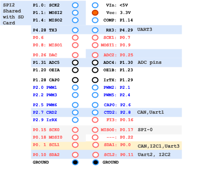
1. UART Pin Mapping for SJ-2 Board
| SJ2 UART's | TXD | RXD | Multiplexed |
| UART 0 | P0.2 | P0.3 | Bootloader, Serial Debug Output |
| P0.0 | P0.1 | CAN1,I2C1 | |
| UART 1 | P0.15 | P0.16 | SSP0 |
| P2.0 | P2.1 | PWM1 | |
| UART 2 | P0.10 | P0.11 | I2C2 |
| P2.8 | P2.9 | Wi-Fi | |
| UART 3 | P0.0 | P0.1 | CAN1,I2C1 |
| P0.25 | P0.26 | ADCx | |
| P4.28 | P4.29 | Wi-Fi | |
| UART 4 | P0.22 | P2.9 | |
| P1.29 | P2.9 |
2. SSP/SPI Pin Mapping for SJ-2 Board
| SJ2 SPI's | SCK | MISO | MOSI |
| SSP0 | P0.15 | P0.17 | P0.18 |
| P1.20 | P1.23 | P1.24 | |
| SSP1 | P0.7 | P0.8 | P0.9 |
| SSP2 | P1.19 | P1.18 | P1.22 |
| P1.31 | P1.18 | P1.22 |
3. I2C Pin Mapping for SJ-2 Board
| SJ2 I2C's | SDA | SCL | Multiplexed |
| I2C 0 | P1.30 | P1.31 | ADCx |
| I2C 1 | P0.0 | P0.1 | UART0, UART3, CAN1 |
| I2C 2 | P0.10 | P0.11 | UART2 |
| P1.15 | P4.29 |
4. CAN Pin Mapping for SJ-2 Board
| SJ2 CAN's | RD | TD | Multiplexed |
| CAN1 | P0.0 | P0.1 | UART0, I2C1, UART3 |
| P0.0 | P0.22 | ||
| CAN2 | P2.7 | P2.8 |
Pin functionality Selection
A pin's functionality may be selected based on your system design. Here are a few examples:
Select UART3 on P4.28 and P4.29:
#include "gpio.h"

void select_uart3_on_port4(void) {
  // Reference "Table 84" at "LPC408x_7x User Manual.pdf"
  gpio__construct_with_function(GPIO__PORT_4, 28, GPIO__FUNCTION_2); // P4.28 as TXD3
  gpio__construct_with_function(GPIO__PORT_4, 29, GPIO__FUNCTION_2); // P4.29 as RXD3
}
A pin function should be set based on one of the 8 possibilities. Here is an example again that sets P0.0 and P0.1 to UART3 (note that the 010 corresponds to GPIO__FUNCTION_2). Of course you can also configureP0.0 and P0.1 as UART0 pins by using GPIO__FUNCTION_4
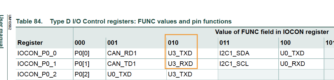
#include "gpio.h"

void select_uart3_on_port0(void) {
  gpio__construct_with_function(GPIO__PORT_0, 0, GPIO__FUNCTION_2); // P0.0 as TXD3
  gpio__construct_with_function(GPIO__PORT_0, 1, GPIO__FUNCTION_2); // P0.1 as RXD3
}
Software Reference
This section focuses on the C software framework, and not the C++ sample project.
CLI Commands
CLI stands for Command Line Interface. The SJ2 C framework includes a way to interact with the board through a CLI command utilizing a CLI task. You can and should add more commands as needed to provide debugging and interaction capability with your board.
You can add your own CLI command by following the steps below:
Step 1: Declare your CLI handler function, the parameters of this function are:
-
app_cli__argument_t: This is not utilized in the SJ2 project, and will beNULL -
sl_string_s: There is a powerful string library type. The string is set to parameters of a CLI command, so if the command name istaskcontroland user inputstaskcontrol suspend led, then the string value will be set tosuspend ledwith the command name removed, seesl_string.hfor more information -
cli_output: This is a function pointer that you should use to output the data back to the CLI
// TODO: Add your CLI handler function declaration to 'cli_handlers.h'
app_cli_status_e cli__your_handler(app_cli__argument_t argument, sl_string_s user_input_minus_command_name,
                                   app_cli__print_string_function cli_output);
Step 2: Add your CLI handler
// TODO: Declare your CLI handler struct, and add it at 'sj2_cli.c' inside the sj2_cli__init() function
void sj2_cli__init(void) {
  // ...
  static app_cli__command_s your_cli_struct = {.command_name = "taskcontrol",
                                               .help_message_for_command = "help message",
                                               .app_cli_handler = cli__your_handler};

  // TODO: Add the CLI handler:
  app_cli__add_command_handler(&sj2_cli_struct, &your_cli_struct);
}
Step 3: Handle your CLI command
// TODO: Add your CLI handler function definition to 'handlers_general.c' (You can also create a new *.c file)
app_cli_status_e cli__your_handler(app_cli__argument_t argument, sl_string_s user_input_minus_command_name,
                                   app_cli__print_string_function cli_output) {
  void *unused_cli_param = NULL;
  // sl_string is a powerful string library, and you can utilize the sl_string.h API to parse parameters of a command

  // Sample code to output data back to the CLI
  sl_string_s s = user_input_minus_command_name; // Re-use a string to save memory
  sl_string__printf(s, "Hello back to the CLI\n");
  cli_output(unused_cli_param, sl_string__c_str(s));

  return APP_CLI_STATUS__SUCCESS;
}

// TODO: Now, when you flash your board, you will see your 'taskcontrol' as a CLI command
Platform Glue
TODO
Newlib and floating point printf and scanf
At the env_arm file, there are a couple of lines you can comment out to save about 18K of flash space. This space is not significant enough when you realize the fact that the LPC controller has 512K of flash ROM space, but it increases a few seconds of programming time each and every time you program.
    LINKFLAGS=[
        # Use hash sign to comment out the line
        # This will disable ability to do printf and scanf of %f (float)
        # "-u", "_printf_float",
        # "-u", "_scanf_float",
Layout a plan or design of something that is laid out More (Definitions, Synonyms, Translation)
RTOS Trace
Overview
FreeRTOS trace is a third party library developed by Percepio; please check them out here. What you can do is to capture the RTOS trace on the micro-sd card on your SJ2 board which you can later plot out to be able to visualize everything that the RTOS is trying to do.
Install
To get started, you first need to install a Windows trace file viewer. This will open up the trace file saved by the SJ2 board for you to visualize all of the data. You can evaluate the product or get student license for free. Please proceed by visiting the following link:
https://percepio.com/downloadform/
Configure
Now that you have installed the Percepio Trace, it is time to configure the SJ2 software to generate the trace. This is super easy to do:
- First, make sure you have a micro SD card installed on the SJ2 board and formatted in FAT32 format
- Go to
FreeRTOSConfig.hand change this macro#define configENABLE_TRACE_ON_SD_CARD 0
That is pretty much it... you can now compile, and flash the new application and the software will save a file called trace.psf onto the SD card's file system. If you do not see the SD Card blinky light a few times each second, you have likely not loaded the correct application onto the board.
Usage
FreeRTOS Trace can be enabled at FreeRTOS_config.h You can open up an example trace from this Gitlab link which has a pre-existing RTOS trace file generated by the SJ2 board.
There is no general need on how to use the API on the SJ2 board related to the RTOS trace, and the bulk of the "usage" is actually opening up the trace file in Percepio Tracalyzer program. The one thing you could do is "printf" trace data that can be visualized in the trace.
void trace_print(void) {
  traceString trace_channel = xTraceRegisterString("trace channel description");

  vTracePrintF(trace_channel, "%d: %d", 1, 234);
}
Standart Output
This article provides useful information about how the standard output is handled on the SJ2 platform.
printf
The standard output is connected to UART0. In a bare metal system without the operating system providing means of outputting data to a console, responsibility lies on the developer to connect printf() to your way of outputting data.
In GCC, the function _write() is invoked for all data output related to file handles. On the SJ2 platform, the function is implemented to output data to UART0, which is connected to the USB to serial chip that is interfaced to a computer (such as windows, linux) to see the serial console.
system_calls.c can be referenced to see the full implementation.
int _write(int file_descriptor, const char *ptr, int bytes_to_write) {
    // ...
    if (rtos_is_running && transmit_queue_enabled && !is_standard_error) {
      system_calls__queued_put(ptr, bytes_to_write);
    } else {
      system_calls__polled_put(ptr, bytes_to_write);
    }

    return bytes_to_write;
}
fprintf
When fprintf(stderr, "...") is utilized, the system_calls.c does not deposit data to an RTOS queue in which case the data would have been sent out "later" depending on the speed of the UART. The stderr is the key that differentiate polled vs. queued data output.
When the stderr is utilized, this "file handle" triggers the branch statement to output the data using polled UART driver. This means that the CPU cycles will be compromised, and we will waste cycles waiting for data to be sent, so this should not be used in "production code".
printf inside of an ISR
Inside of an interrupt, you never want to "block" using any RTOS API. If we use standard printf(), it may try to enqueue the data to be sent out of the UART0 peripheral, and therefore may crash the system when the UART transmission queue becomes full (as it will then try to sleep on the queue to be not full). Because of this, fprintf(stderr, "...") may be utilized inside of an ISR as it would not enqueue the data or try to "block" through the RTOS API.
In "production intent" code, there should be no printfs inside of an ISR.