
Lab: ADC + PWM
Objective
Improve an ADC driver, and use an existing PWM driver to design and implement an embedded application, which uses RTOS queues to communicate between tasks.
This lab will utilize:
- ADC Driver
- You will improve the driver functionality
- You will use a potentiometer that controls the analog voltage feeding into an analog pin of your microcontroller
- PWM Driver
- You will use an existing PWM Driver to control a GPIO
- An led brightness will be controlled, or you can create multiple colors using an RGB LED
- FreeRTOS Tasks
- You will use FreeRTOS queues
Assignment
Preparation:
Before you start the assignment, please read the following in your LPC User manual (UM10562.PDF)
- Chapter 7: I/O configuration
- Chapter 32: ADC
Part 0: Use PWM1 driver to control a PWM output pin
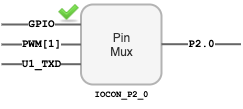
The first thing to do is to select a pin to function as a PWM signal. This means that once you select a pin function correctly, then the pin's function is controlled by the PWM peripheral and you cannot control the pin's HIGH or LOW using the GPIO peripheral. By default, a pin's function is as GPIO, but for example, you can disconnect this function and select the PWM function by using the IOCON_P2_0
- Re-use the PWM driver
- Study the
pwm1.handpwm1.cfiles underl3_driversdirectory
- Study the
- Locate the pins that the PWM peripheral can control at
Table 84: FUNC values and pin functions- These are labeled as
PWM1[x]wherePWM1is the peripheral, and[x]is a channel- So
PWM1[2]means PWM1, channel 2
- So
- Now find which of these channels are available as a free pin on your SJ2 board and connect the RGB led
- Set the
FUNCof the pin to use this GPIO as a PWM output
- Set the
- These are labeled as
- Initialize and use the PWM-1 driver
- Initialize the PWM1 driver at a frequency of your choice (greater than 30Hz for human eyes)
- Set the duty cycle and let the hardware do its job :)
- You are finished with Part 0 if you can demonstrate control over an LED's brightness using the HW based PWM method
#include "pwm1.h"

#include "FreeRTOS.h"
#include "task.h"

void pwm_task(void *p) {
  pwm1__init_single_edge(1000);

  // Locate a GPIO pin that a PWM channel will control
  // NOTE You can use gpio__construct_with_function() API from gpio.h
  // TODO Write this function yourself
  pin_configure_pwm_channel_as_io_pin();

  // We only need to set PWM configuration once, and the HW will drive
  // the GPIO at 1000Hz, and control set its duty cycle to 50%
  pwm1__set_duty_cycle(PWM1__2_0, 50);

  // Continue to vary the duty cycle in the loop
  uint8_t percent = 0;
  while (1) {
    pwm1__set_duty_cycle(PWM1__2_0, percent);

    if (++percent > 100) {
      percent = 0;
    }

    vTaskDelay(100);
  }
}

void main(void) {
  xTaskCreate(pwm_task, ...);
  vTaskStartScheduler();
}
Part 1: Alter the ADC driver to enable Burst Mode
- Study
adc.handadc.cfiles inl3_driversdirectory and correlate the code with the ADC peripheral by reading the LPC User Manual.- Do not skim over the driver, make sure you fully understand it.
- Identify a pin on the SJ2 board that is an ADC channel going into your ADC peripheral.
- Reference the I/O pin map section in
Table 84,85,86: FUNC values and pin functions
- Reference the I/O pin map section in
- Connect a potentiometer to one of the ADC pins available on SJ2 board. Use the ADC driver and implement a simple task to decode the potentiometer values and print them. Values printed should range from 0-4095 for different positions of the potentiometer.
// TODO: Open up existing adc.h file
// TODO: Add the following API

/**
 * Implement a new function called adc__enable_burst_mode() which will
 * set the relevant bits in Control Register (CR) to enable burst mode.
 */
void adc__enable_burst_mode(void);

/**
 * Note:
 * The existing ADC driver is designed to work for non-burst mode
 *
 * You will need to write a routine that reads data while the ADC is in burst mode
 * Note that in burst mode, you will NOT read the result from the GDR register
 * Read the LPC user manual for more details
 */
uint16_t adc__get_channel_reading_with_burst_mode(uint8_t channel_number);
#include "adc.h"

#include "FreeRTOS.h"
#include "task.h"

void adc_pin_initialize(void) {
  // TODO: Ensure that you also set ADMODE to 0
  // TODO: Ensure you set pull/up and pull/down bits 0
  // TODO: Then use gpio__construct_with_function(...)
}

void adc_task(void *p) {
  adc_pin_initialize();
  adc__initialize();

  // TODO This is the function you need to add to adc.h
  // You can configure burst mode for just the channel you are using
  adc__enable_burst_mode();

  // Configure a pin, such as P1.31 with FUNC 011 to route this pin as ADC channel 5
  // You can use gpio__construct_with_function() API from gpio.h
  pin_configure_adc_channel_as_io_pin(); // TODO You need to write this function

  while (1) {
    // Get the ADC reading using a new routine you created to read an ADC burst reading
    // TODO: You need to write the implementation of this function
    const uint16_t adc_value = adc__get_channel_reading_with_burst_mode(ADC__CHANNEL_2);

    vTaskDelay(100);
  }
}

void main(void) {
  xTaskCreate(adc_task, ...);
  vTaskStartScheduler();
}
Part 2: Use FreeRTOS Queues to communicate between tasks
- Read this chapter to understand how FreeRTOS queues work
- Send data from the
adc_taskto the RTOS queue - Receive data from the queue in the
pwm_task
#include "adc.h"

#include "FreeRTOS.h"
#include "task.h"
#include "queue.h"

// This is the queue handle we will need for the xQueue Send/Receive API
static QueueHandle_t adc_to_pwm_task_queue;

void adc_task(void *p) {
  // NOTE: Reuse the code from Part 1

  int adc_reading = 0; // Note that this 'adc_reading' is not the same variable as the one from adc_task
  while (1) {
    // Implement code to send potentiometer value on the queue
    // a) read ADC input to 'int adc_reading'
    // b) Send to queue: xQueueSend(adc_to_pwm_task_queue, &adc_reading, 0);
    vTaskDelay(100);
  }
}

void pwm_task(void *p) {
  // NOTE: Reuse the code from Part 0
  int adc_reading = 0;

  while (1) {
    // Implement code to receive potentiometer value from queue
    if (xQueueReceive(adc_to_pwm_task_queue, &adc_reading, 100)) {
    }

    // We do not need task delay because our queue API will put task to sleep when there is no data in the queue
    // vTaskDelay(100);
  }
}

void main(void) {
  // Queue will only hold 1 integer
  adc_to_pwm_task_queue = xQueueCreate(1, sizeof(int));

  xTaskCreate(adc_task, ...);
  xTaskCreate(pwm_task, ...);
  vTaskStartScheduler();
}
Part 3: Allow the Potentiometer to control the RGB LED
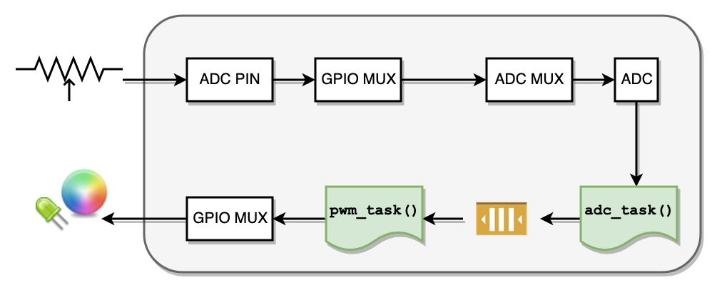
At this point, you should have the following structure in place:
- ADC task is reading the potentiometer ADC channel, and sending its values over to a queue
- PWM task is reading from the queue
Your next step is:
- PWM task should read the ADC queue value, and control the an LED
Final Requirements
Minimal requirement is to use a single potentiometer, and vary the light output of an LED using a PWM. For extra credit, you may use 3 PWM pins to control an RGB led and create color combinations using a single potentiometer.
- Make sure your Part 3 requirements are completed
-
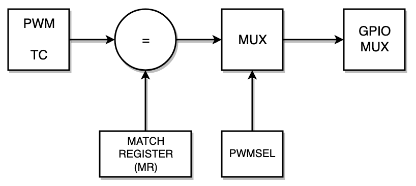
pwm_taskshould print the values of MR0, and the match register used to alter the PWM LEDs- For example, MR1 may be used to control P2.0, so you will print MR0, and MR1
- Use memory mapped
LPC_PWMregisters fromlpc40xx.h
- Make sure BURST MODE is enabled correctly.
-
adc_taskshould convert the digital value to a voltage value (such as 1.653 volts) and print it out to the serial console- Remember that your VREF for ADC is 3.3, and you can use ratio to find the voltage value
adc_voltage / 3.3 = adc_reading / 4095