
Lab Assignment: UART
Objective
To learn how to communicate between two master devices using UART.
Assignment
This assignment will require two boards. The overall idea is to interface two boards using your UART driver. To test you can use a single board and perform a UART loopback (tie your own RX and TX wires together) in order to ensure that your driver is functional before trying to put two boards together.
Part 0: Get the simplest UART driver to function correctly
First, individually, get the simplest UART driver to work. Here is the rough skeleton:
// WARNING: Some of this is psuedocode, so you figure it out
void Uart2Interrupt()
{
  // TODO: Queue your data and clear UART Rx interrupt
}

void InitializeUart2()
{
  // Init PINSEL, baud rate, frame size, etc.
  // Init UART Rx interrupt (TX interrupt is optional)
  RegisterIsr(Uart2, Uart2Interrupt);
}

void Uart2Send(/* fill this out */)
{
  // Send data via uart
}
void Uart2Recieve(/* fill this out */)
{
  // Send data via uart
}

void vSendOverUartTask(void * pvParamater)
{
  while (true)
  {
    Uart2Send(/* some data */);
    vTaskDelay(1000);
  }
}

void vRecieveByteOverUartTask(void * pvParamater)
{
  while (true)
  {
    if (xQueueReceive(/* ... */, portMAX_DELAY))
    {
      printf("Got %c char from my UART... job is half done!");
    }
  }
}

void main(void)
{
  InitializeUart2();
  CreateTasks();
}
HINT: You can test that your transmit and receive are working with only one SJOne board if you use a jumper to connect your UART TX and RX together. This is called a loopback test.
Part 1: Design UART driver
Using the following class template
- Design a UART driver as you have the previous drivers.
- Implement any functionality you deem useful for a general purpose UART driver.
- Document/comment each method and variable within the class template.
#pragma once

class LabUart
{
 public:
  // TODO: Fill in methods for Initialize(), Transmit(), Receive() etc.
  //
  // Optional: For the adventurous types, you may inherit from "CharDev" class
  // to get a lot of functionality for free
 private:
};
Code Block 1. UART Driver Template Class
Part 2: Serial Application
For this application, one device will ask the other device to calculate the result of two numbers and an operation.
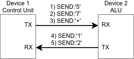
Figure 1
Think about it like this, using figure 1 as a guide:
- Device 1 sends a single digit '5', Device 2 receives single digit '5'
- Device 1 sends another single digit '7', device 2 receives single digit '7'
- Device 1 sends an operator '+', device 2 receives operator '+' and computes the result.
- Device 2 sends result back to device 1.
When the result is calculated, both the devices oled displays should show that resultant.
You MAY use the pre-written OLED driver for this lab.
Requirements
- Design UART driver to work with both UART2 and UART3
- UART receive should be interrupt driven
- When data arrives, store it to a FreeRTOS queue inside of the UART RX interrupt
- UART receive function should dequeue the data
- ALU application must be able to support the following operators
- + Addition
- - Subtraction
- * Multiplication
What to turn in:
- Submit all relevant files and files used (includes previous lab code used).
- Turn in any the screenshots of terminal output.
- Logic Analyzer Screenshots
- Waveform of device 1 UART TX sending a digits and operator to device 2.
- These can be in separate images if you can't fit everything in one image.
- Waveform of device 2 UART TX sending result back to device 1.
- Whole window screenshot with the Decoded Protocols (lower right hand side of window) clearly legible.
- Waveform of device 1 UART TX sending a digits and operator to device 2.
Extra Credit
Use the on-board buttons and OLED display as human interface devices (HID) and allow the user to punch in the numbers and operations in some way. Be creative about this.
If you are doing the extra credit, you may use the the L2/button driver.