
UART
Objective
The objective of this lesson is to understand UART, and use two boards and setup UART communication between them.
UART
UART stands for Universal Asynchronous Receiver-Transmitter.
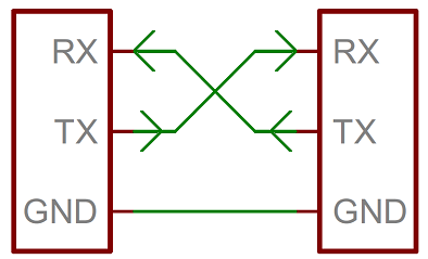
Figure 1. UART connection between two devices.
For Universal Asynchronous Receiver Transmitter. There is one wire for transmitting data (TX), and one wire to receive data (RX). It is asynchronous because there is no clock line between two UART hosts.
BAUD Rate
A common parameter is the baud rate known as "bps" which stands for bits per second. If a transmitter is configured with 9600bps, then the receiver must be listening on the other end at the same speed. Using the 9600bps example, each bit time is 1 / 9600 = 104uS. That means that if a transmitter wants to transmit a byte, it must do so by latching one bit on the wire, and then waiting 104uS before another bit is latched on the wire.
If you were to take a GPIO, and emulate UART at 9600 to send out a byte of data, it would look like this:
// Assumes GPIO is a memory that can set level of a Port/Pin (psuedocode)
void uart_send_at_9600bps(const char byte) {
  // 9600bps means each bit lasts on the wire for 104uS (approximately)
  GPIO = 0; delay_us(104); // Start bit is LOW

  // Check if bit0 is 1, then set the GPIO to HIGH, otherwise set it to LOW
  GPIO = (byte & (1 << 0)) ? 1 : 0; delay_us(104); // Use conditional statement
  GPIO = (bool) (byte & (1 << 1)); delay_us(104);  // Case to bool
  GPIO = (byte & (1 << 2)); delay_us(104);
  GPIO = (byte & (1 << 3)); delay_us(104);

  GPIO = (byte & (1 << 4)); delay_us(104);
  GPIO = (byte & (1 << 5)); delay_us(104);
  GPIO = (byte & (1 << 6)); delay_us(104);
  GPIO = (byte & (1 << 7)); delay_us(104);

  GPIO = 1; delay_us(104); // STOP bit is HIGH
}
UART Frame
UART is a serial communication, so bits must travel on a single wire. If you wish to send a 8-bit byte (uint8_t) over UART, the byte is enclosed within a start and a stop bit. Therefore, to transmit a byte, it would require 2-bits of overhead; this 10-bit of information is called a UART frame. Let's take a look at how the character 'A' is sent over UART. In ASCII table, the character 'A' has the value of 65, which in binary is: 0100_0001. If you inform your UART hardware that you wish to send this data at 9600bps, here is how the frame would appear on an oscilloscope :
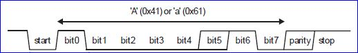
Figure 2. UART Frame sending letter 'A'
UART Ports
Benefits
- Hardware complexity is low.
- No clock signal needed
- Has a parity bit to allow for error checking
- As this is one to one connection between two devices, device addressing is not required.
Drawbacks
- The size of the data frame is limited to a maximum of 8 bits (some micros may support non-standard data bits)
- Doesn’t support multiple slave or multiple master systems
- The baud rates of each UART must be within ~3% (or lower, depending on device tolerance) of each other
Hardware Design
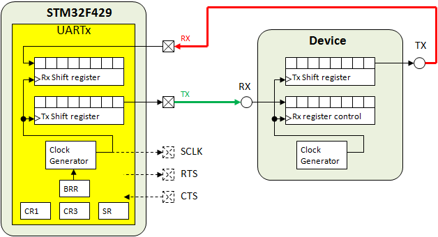
Figure 3. Simplified UART peripheral design for the STM32F429. SCLK is used for USART.
WARNING: The above is missing a common ground connection
Software Driver
The UART chapter on LPC40xx has a really good summary page on how to write a UART driver. Read the register description of each UART register to understand how to write a driver.
Memory Shadowing in UART driver
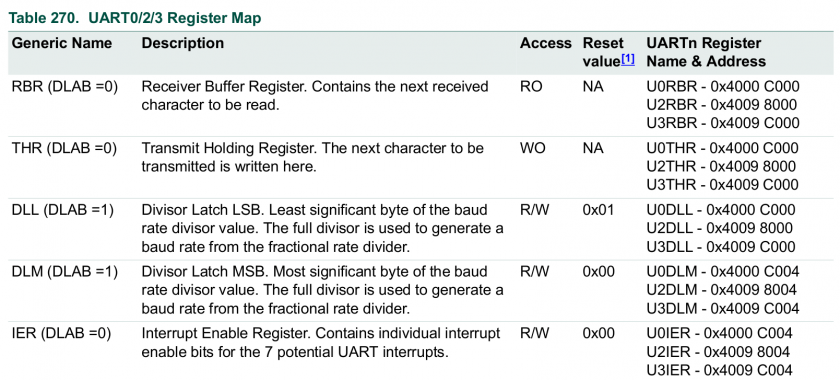
Figure 4. Memory Shadowing using DLAB Bit Register
In figure 4, you will see that registers RBR/THR and DLL have the same address 0x4000C000. These registers are shadowed using the DLAB control bit. Setting DLAB bit to 1 allows the user to manipulate DLL and DLM, and clearing DLAB to 0 will allow you to manipulate the THR and RBR registers.
The reason that the DLL register shares the same memory address as the RBR/THR may be historic. My guess is that it was intentionally hidden such that a user cannot accidentally modify the DLL register. Even if this case is not very significant present day, the manufacturer is probably using the same UART verilog code from many decades ago.
Control Space Divergence (CSD) in UART driver
In figure 4, you will see that register RBR and THR have the same address 0x4000C000. But also notice that access to each respective register is only from read or write operations. For example, if you read from memory location 0x4000C000, you will get the information from receive buffer and if you write to memory location 0x4000C000, you will write to a separate register which the transmit holding register. We call this Control Space Divergence since access of two separate registers or devices is done on a single address using the read/write control signal is used to multiplex between them. That address is considered to be Control Space Divergent. Typically, the control space aligns with its respective memory or io space.
Note that Control Space Divergence does not have a name outside of this course. It is Khalil Estell's phrase for this phenomenon.
BAUD Rate Formula
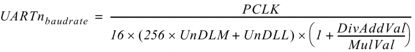
Figure 5. Baud rate formula
To set the baud rate you will need to manipulate the DLM and DLL registers. Notice the 256*UnDLM in the equation. That is merely another way to write the following (DLM << 8). Shifting a number is akin to multiplying it by 2 to the power of the number of shifts. DLM and DLL are the lower and higher 8-bits of a 16 bit number that divides the UART baudrate clock. DivAddVal and MulVal are used to fine tune the BAUD rate, but for this class, you can simply get "close enough" and ignore these values. Take these into consideration when you need an extremely close baudrate.
Advanced Design
If you used 9600bps, and sent 1000 characters, your processor would basically enter a "busy-wait" loop and spend 1040ms to send 1000 bytes of data. You can enhance this behavior by allowing your uart send function to enter data to a queue, and return immediately, and you can use the THRE or "Transmitter Holding Register Empty" interrupt indicator to remove your busy-wait loop while you wait for a character to be sent.